
INTRODUCTION
This Project implements some applications which makes use of the 3 – axis accelerometer LIS3LV02DL. The project uses the STM32F103ZE high-performance ARM® CortexTM-M3 32-bit RISC core operating at a 72 MHz frequency. The applications we included in this are
1.ROLE and AMAZE
2.POSITION DETECTION
3.CALENDER
4.CALCULATOR
ROLE AND AMAZE
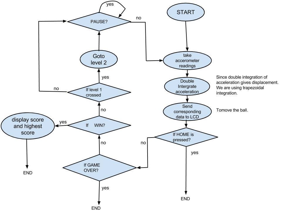
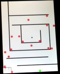
This is a game where there will be a ball which moves in the way you move your board. There will be mazes with traps in between. we should make the ball follow the maze with out touching the traps. This way it should complete the path and reach the destination with in the lap time. Lesser the time you take to complete the maze, more you score. You will lose the game if your ball touches the traps on your path or if you run out of lap time.
There are two levels of maze. once you complete first maze, it will directly take you to second level. after you completing the second level, it will display your score and highest score achieved.In between if you get in to traps or if you run out of time, the game will end right away.
CALENDER
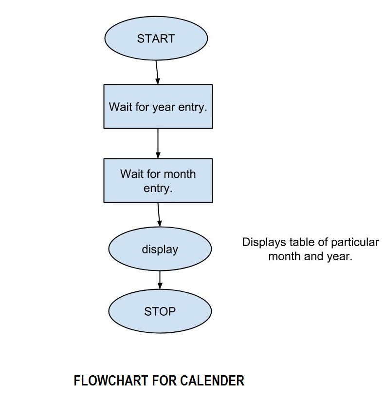
The calender is capable to show any date started from 1800 to any further years. At the first window you need to select a year and the respective month, based on that a day chart will appear on the next page. To swipe the years two buttons are available PREV(previous) and NEXT which will navigate you to ten new years among which you need to select one.
CALCULATOR
This is an application which will do basic arithmetic operations addition, subtraction, multiplication, division and modulous. result will be displayed on LCD screen.
THEORY AND ALGORITHM FOR ROLE AND MAZE
As we know the velocity is the derivative of the position and the acceleration is the derivative of the velocity, thus:
   a = dv/dt and v = ds/dt
   so a  = d(ds)/dt2
      v = ∫a dt and
      s = ∫(∫a dt)dt.
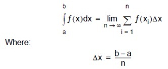
Integration is the area under the curve. It can be approximated to the sum of the very small areas whose width is tending to zero.
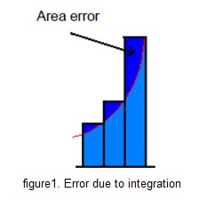
but this approach results in the area error, which keep on accumulating for the time the process is active. This area error is reduced by the first order approximation so called Trapezodial Method.
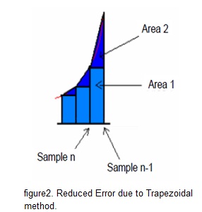
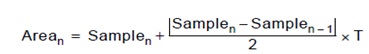
The first area is the value of the previous sample (a square). The second area is a triangle, formed between the previous sample (sample n-1) and the actual sample (sample n) divided by two.
SOFTWARE DESIGN CONSIDERATION
FFor real time implementation of the algorithm, the following steps are used:
1. Data sensed by accelerometer is noisy. So averaging filter is used
2. Even with the previous filtering some data can be erroneous due to the mechanical noise, so another filter is implemented. Depending on the number of samples used for filtering, a window of real acceleration is selected.
3. Calibration is done to remove the acceleration offset.
4. Actual acceleration value is the sample minus the calibrated value.
5. Time between the acceleration samples must be same otherwise error is generated.
6. Create the mazes on the screen, This can be made easy by defining macros for obstacles. after that its just about calling these macros to create obstacles.
7. Create pot-holes in the path through which ball has to go towards the destination if ball get into it the game should be over.
8. Track the time, taken by the ball to reach to the destination and generate a score accordingly. lesser the time you take to clear the maze, more the score you get.
9. Lap time out condition, This limits your lap time. clearing the maze, if you run out of time in between, the game should be over.
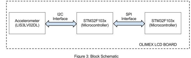
BLOCK DIAGRAM
FLOW CHART
FLOW CHART FOR ROLL AND MAZE GAME
FLOW CHART FOR CALENDER
ACCELEROMETER CONFIGURATION
The Accelerometer LIS3LV02DL is connected to I2C bus as slave. STM32F103x is master on I2C bus. The GPIO pins PB10 and PB11 (I2C2) are configured in open drain alternate function mode. Also, for required application of position computations, the Control registers of accelerometer module is configured as follows. The detailed description of registers can be found in the datasheet of LIS3LV02DL.
SLAVE ADDRESS = 0x3A
CTRL_REG1 (20h)
![]()
we have configured it as 0xC7, which implies all three axis are enabled, decimation factor of 512 corresponding to 40Hz data rate.
CTRL_REG2 (21h)
![]()
we have configured it as 0x44, which implies no output registers updates while reading, enables the data ready generation and acceleration range as +/- 2g. Also, output data registers are represented in 12 bit right justified mode (2’s complement)i.e for +/- 2g, maximum count would be +/-2048.
CTRL_REG3 (22h)
![]()
we have configured it as 0x10, which implies internal filter is used and filter coefficient(Hpc) = 512.
Related pictures
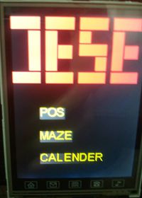
Main Page
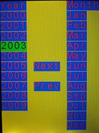
Calender Page 1
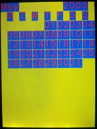
Calender Page 2

MAZE Game Level 1
MAZE Game Level 2
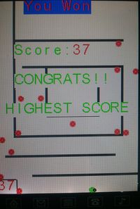
MAZE Game Page after finish two levels
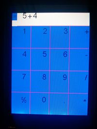
Calculator
REFERENCE
1. Application Note- AN3397
2. Data Sheet STM32F- Datasheet_stm32f103
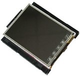
3. Olimax LCD- STM32-LCD_data
PROJECT TEAM
K. Jayanth Kumar
Abhishek Das
Recent Comments