
Introduction
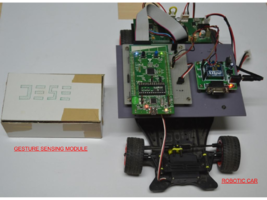
Gesture Sensing Module & Robotic Car
The aim of the mini-project is to make a Gesture Controlled Smart Car that moves left,right, forward direction based on the hand gestures. The gesture is the tilt of the hand with respect to the vertical axis to the ground. There are two parts to this project. The first is a gesture sensing module that is an accelerometer and then there is a steerable robotic car (having on board ARM Cortex-M3 based Discovery Board).
Components Used
The following components are required
- 1. STM32L152 Discovery Board – 2
- 2. Accelerometer (3 axis) – LSM303DLHTR – 1
- 3. XBee Module – 2
- 4. Freescale Smart Car – 1
- 5. Transistors BC547, Resistors, LD33CV, 9V battery
STM32L152 Discovery Board:
-> We used two STM32L152 Discovery Boards one for Gesture Sensing Module & another for Robotic Car.
-> Gesture Sensing Module STM32L152 Discovery Board is interfaced with Accelerometer LSM303DLM to sense the gesture and with XBee Module to send the command to Robotic Car.
-> Robotic Car STM32L152 Discovery Board is interfaced with XBee Module to receive the command from gesture sensing module and to provide PWM to motor driver circuit.

Accelerometer LSM303DLM:
 -> Interfaced with STM32L152 Discovery Board using I2C serial interface.
 -> It is configured for fast mode (400 kHz).
 -> Its address was configured as 0x30 by pulling down SA0 pin.
 -> Linear acceleration register description
    CTRL_REG1_A (20h) is configured as 0x27
    Power mode             -  Normal mode
    Output data rate [Hz]  -  50
    X,Y,Z axis enabled
XBee Module:
 -> Interfaced with STM32L1 Discovery Board using UART interface.
 -> Both modules(Gesture sensing module XBee and Car XBee) are configured as Routers.
 -> UART frame 1-start bit, 8-data bit, no parity and 1 stop bit, No hardware flow control.
 -> Baud Rate is configured as 115200.
 -> Configuration steps.
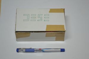
Freescale Smart Car:
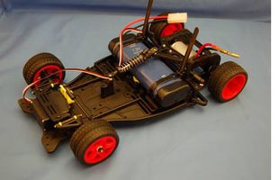
Freescale Smart Car
Gesture Sensing Module
As shown in the figure Gesture Sensing module consists of accelerometer to sense the gesture.
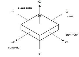
Accelerometer axis
 -> When the module is flat means parallel to ground then X and Y-axis readings are zero
hence robotic car remains still.
 -> In Normal Mode, axis data range from -32768 to +32767 for -2g to +2g.
 -> We get the data in the range -16384 to +16383 for -g to +g.
 -> As we tilt the Gesture Module forward, X-axis value increases.
 -> Similarly if we turn the Y-axis value changes.
 -> The hypotenuse of both the values will always be 1g, so we can also derive one from other.
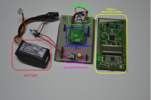
Gesture Sensing Module Unpacked
Gesture Sensing Module
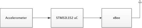
Gesture Sensing Block Diagram
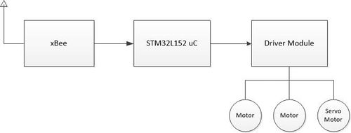
Robotic Car Circuit Block Diagram
Robotic Car
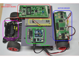
Robotic Car
The Robotic Car consists of a Xbee module for data reception, a STM32 board for PWM generation, a level shifter for changing the voltage level from 3.3V to 5V for servo motor, a motor driver circuit to provide adequate current to the DC motors, a voltage regulator for regulating 7.2V battery voltage to 5V, two DC motors and a servo motor as shown in the following figure.
Analog Circuits used
The servo motor needs 5V PWM for proper functioning. The STM32 board provides 3.3V at its pin. Thus, the following circuits shifts the 3.3V voltage level to 5V level. 5V is taken from motor driver module.
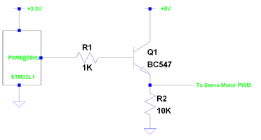
Level Shifter
Design and Algorithm
As mentioned earlier the accelerometer gives data in the range -16384 to +16383 for -1g to +1g. For forward acceleration and turn angle we get a value. We segment this data into 255 blocks after removing an offset of 1000-1500. Since the driver module is unable to drive the motors in reverse direction, for negative values we make the car stop. At transmission we half the forward value and send. The turn angle value is halved and added to 128. At reception, the value which is less than 128 is taken as forward acceleration . The value which is greater than 128 we take it as turn angle and subtract 128 for actual turn angle.
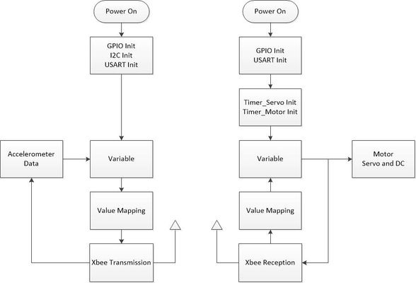
Data Flow
Problems Faced
- 1. The Driver circuit used was provided with Freescale Cup Car. Circuit is made such that the motors can rotate only in one direction. To make motors rotate in both direction, a separate driver circuit has to be made. Proper current protection for the STM32 pin has to be put with the driver as the pin can withstand max 25mA.
Future Work
- 1. The accelerometer value is very fluctuating, we can incorporate some type filter like an averaging loop of last few readings.
- 2. At the receiver side, we can implement time-out feature with the help of a timer, if the Xbee doesnot receive any data for some time.
Demo Video
References
Team Members
Recent Comments