
I INTRODUCTION AND MOTIVATION
Obstacle Avoiding Robot is an intelligent device which can automatically sense the obstacle in front of it and avoid them by turning itself in another direction. This design allows the robot to navigate in unknown environment by avoiding collisions, which is a primary requirement for any autonomous mobile robot. The application of Obstacle Avoiding robot is not limited and it is used in most of the military organization now which helps carry out many risky jobs that cannot be done by any soldiers. Before going to build the robot, it is important to understand how the ultrasonic sensor works because this sensor will have important role in detecting obstacle. The basic principle behind the working of ultrasonic sensor is to note down the time taken by sensor to transmit ultrasonic beams and receiving the ultrasonic beams after hitting the surface. Then further the distance is calculated using the formula. In this project, the widely available HC-SR04 Ultrasonic Sensor is used. To use this sensor, similar approach will be followed explained above.
II BACKGROUND STUDY OF THE ULTRASONIC SENSOR
Ultrasonic ranging module HC – SR04 provides 2cm – 400cm non-contact measurement function, the ranging accuracy can reach to 3mm. The modules include ultrasonic transmitters, receiver and control circuit. The basic principle of work:
1. Using IO trigger for at least 10us high level signal,
2. The Module automatically sends eight 40 kHz and detect whether there is a pulse signal back.
3. If the signal back, through high level, time of high output IO duration is the time from sending ultrasonic to returning.
| Working Voltage | DC 5 V |
| Working Current | 15mA |
| Working Frequency | 40Hz |
| Max Range | 4m |
| Min Range | 2cm |
| Measuring Angle | 15 degree |
| Trigger Input Signal | 10uS TTL pluse |
| Echo Output Signal | Input TTL lever signal and the range in proportion |
| Dimension | 45*29*15mm |
| 4 pins description-
• 5V Supply
|
So, the Trig pin of HC-SR04 is made high for at least 10 us. A sonic beam is transmitted with 8 pulses of 40KHz each.
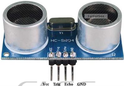
Figure 2: Ultrasonic Sensor
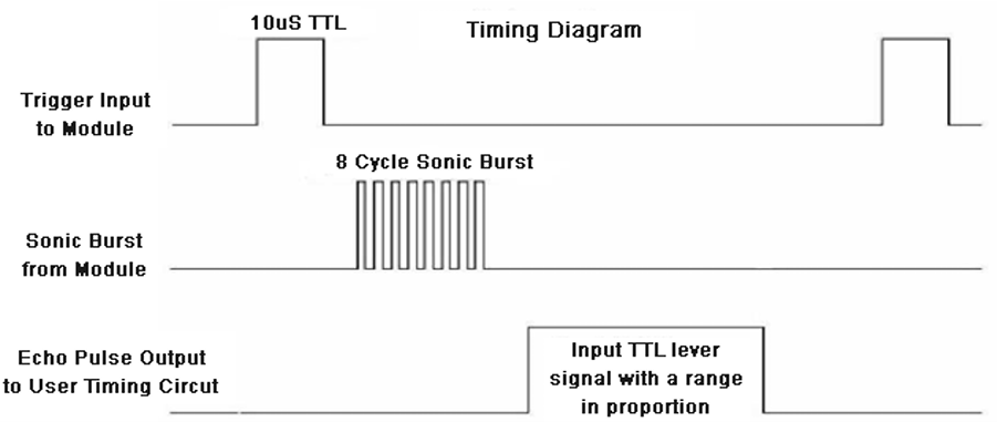
Figure 3: Timing Diagram of Ultrasonic Sensor
The signal then hits the surface and return and captured by the receiver Echo pin of HC-SR04. The Echo pin had already made high at the time sending high.
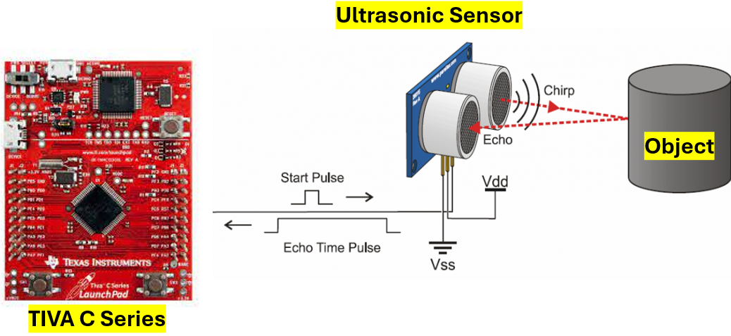
Figure 4: Block Diagram of Ultrasonic Sensor
The time taken by beam to return back is saved in variable and converted to distance using appropriate calculations like below:
Distance = (Time x Speed of Sound in Air (343 m/s))/2
III ARCHITECTURAL DESIGN SPACE EXPLORATION AND DESIGN STRATEGIES
3.1 Components Used
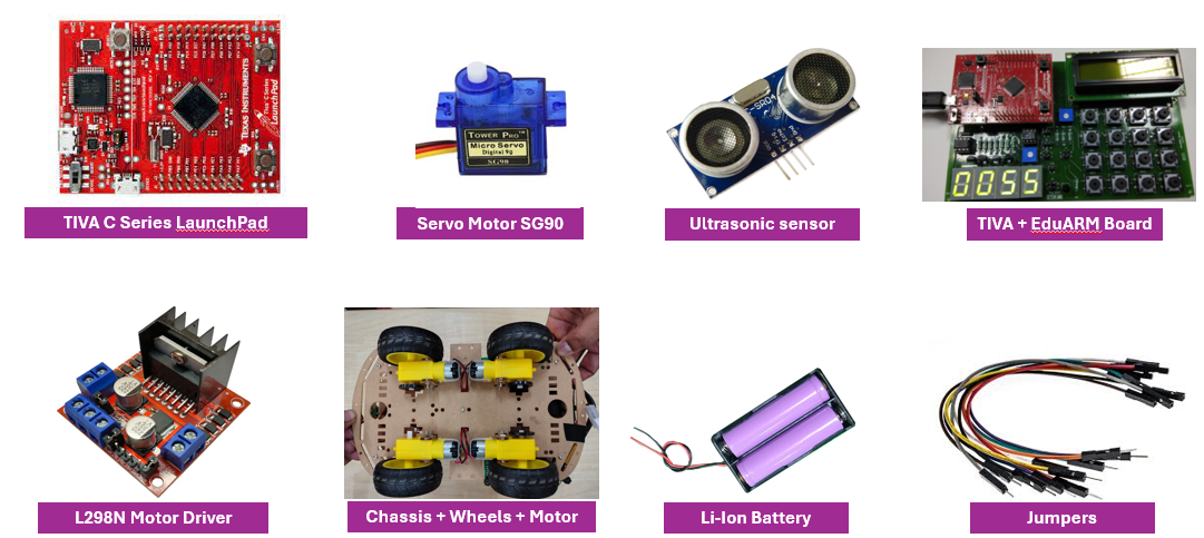
Figure 5: Components Used
3.2 Design of Hardware and mounting components
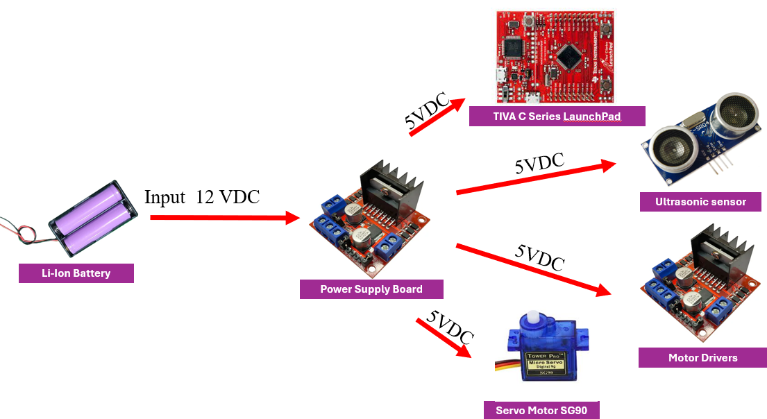
Figure 6: Design of Hardware and mounting components
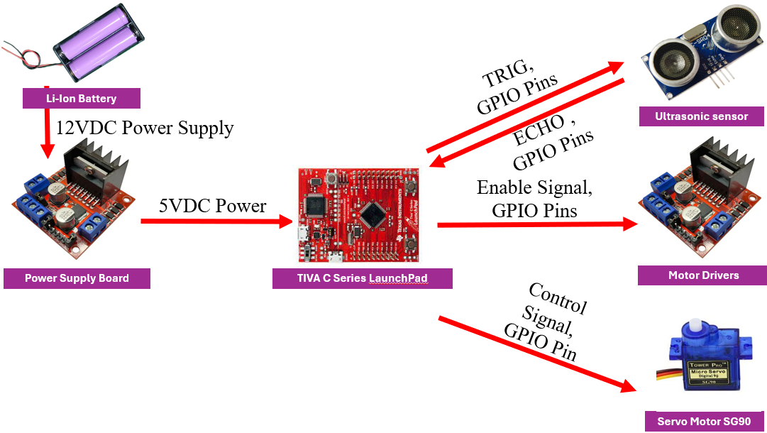
Figure 7: Power Diagram
3.3 Circuit Schematics
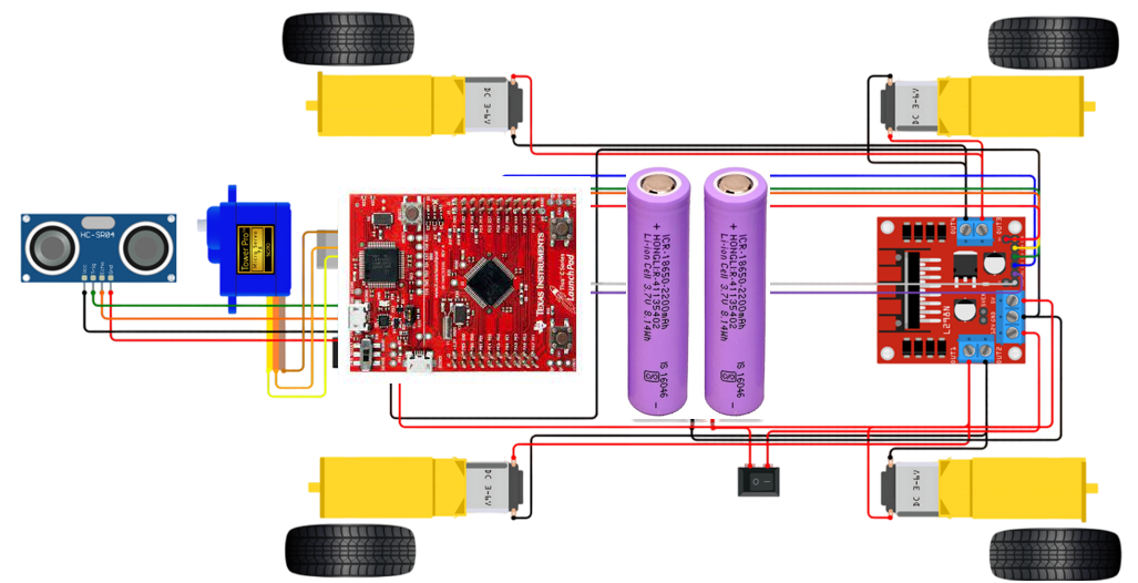
Figure 8: Circuit Schematics
IV SOFTWARE ALGORITHM
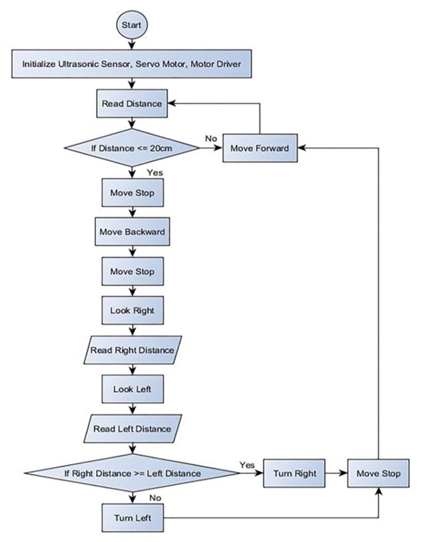
Figure 9: Software Algorithm
V DETAILED ANALYSIS OF TM4C123G-BASED EMBEDDED SYSTEM
5.1Peripheral Connections
The following table summarizes the key connections between the TM4C123G LaunchPad and the peripherals through the Ed-uARM4 board:
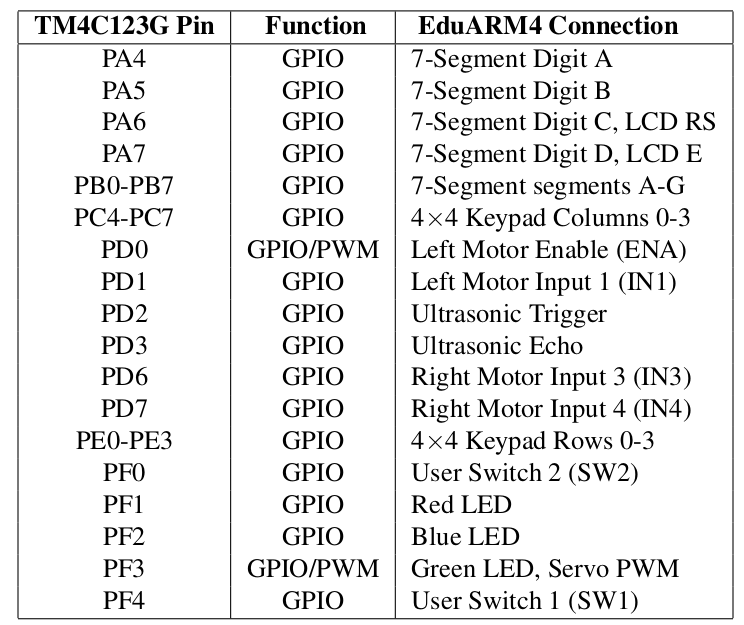
5.2 Peripheral Interfaces
5.2.14×4 Keypad Matrix
The 4×4 keypad is connected to Port E (rows, PE0-PE3) and Port C (columns, PC4-PC7). The keypad is scanned using a standard matrix approach:
1. All rows are driven low to detect if any key is pressed.
2. When a key press is detected, rows are scanned one by one to identify the exact key.
3. Debouncing is implemented to avoid multiple detections from a single key press.
The keypad implementation includes functions for initialization (Keypad Init), checking for key presses (Key- pad IsKeyPressed), and retrieving the pressed key value (Keypad GetKey). The system uses the keypad for timer input in one of the application modes.
Key Mapping:
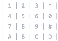
Figure 10: Keypad Mapping
5.2.2 7-Segment Display
The 7-segment display interface uses Port B (PB0-PB7) for segment control and Port A (PA4-PA7) for digit selection in a multiplexed configuration. The display is capable of showing:
• Numeric digits (0-9)
• Alphabetic characters (with limited representation)
• Special characters (decimal point, dash, etc.)
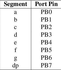
Segment Mapping:
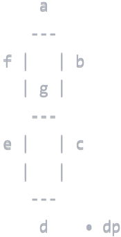
Figure 11: Segment Mapping
5.2.3 16×2 LCD Interface
The 16×2 LCD display uses the industry-standard HD44780 controller and is connected in 8-bit mode:
• Data lines (D0-D7): PB0-PB7
• Register Select (RS): PA6
• Enable (E): PA7
• Read/Write (R/W): Grounded (write-only mode)
The LCD interface provides functions for initialization (init LCD)), sending commands (LCD Command), sending data (LCD Data)), and printing strings to specified lines (LCD Print). It supports standard HD44780 commands for clearing the display, positioning the cursor, and controlling display properties. Example usage in the code shows displaying status messages, timer values, and robot state information.
5.2.4 Ultrasonic Sensor
The ultrasonic sensor (likely HC-SR04) is connected to:
• Trigger pin: PD2
• Echo pin: PD3
The implementation uses a timer (Timer0) for precise time measurement and GPIO interrupts on the echo pin to capture pulse width:
1. A 10ÎŒs pulse is sent on the trigger pin.
2. The system waits for the echo pin to go high (rising edge).
3. When the echo pin goes high, the timer value is captured.
4. When the echo pin goes low (falling edge), the timer value is captured again.
5. The difference between timer values is used to calculate distance.
The implementation includes functions for initialization (ultrasonicInit), triggering measurements (triggerUltrasonic), and retrieving the measured distance (getDistance).
5.2.5 Motor Control
The system uses a dual motor driver (likely an L298N or similar H-bridge driver) controlled through:
• Left Motor: Enable (ENA): PD0, Input 1 (IN1): PD1, Input 2 (IN2): PA2.
• Right Motor: Enable (ENB): PA3, Input 3 (IN3): PD6, Input 4 (IN4): PD7.
The motor control implementation includes:
• Software PWM for speed control through enable pins.
• Direction control through input pins.
• Functions for common operations: forward, backward, stop, turn left/right, rotate left/right.
• Special braking functions: (motors brake reverse) and (motors emergency stop).
The PWM update is handled through SysTick interrupts to maintain consistent speed control.
5.2.6 Servo Motor
The servo motor is controlled using hardware PWM on PF3 (which coincides with the green LED). The implementation uses:
• PWM Module 1, Generator 3, Output 7 (M1PWM7).
• 50Hz frequency (20ms period) – standard for servo motors.
• Pulse width range: 500 µs (0°) to 2500 µs (180°).
The servo control includes functions for initialization (servoInit), setting a specific angle (servoSetAngle), and convenience functions for common positions: left, center, and right.
The servo motor is used for scanning the environment during obstacle detection, with left and right positions corresponding to -90°and +90°relative to the center position.
VI SOFTWARE ARCHITECTURE
6.1 GPIO Configuration
The GPIO configuration is systematically organized with separate initialization functions for each port:
• (init PORTA) , (init PORTB), etc. for individual port setup.
• (Init Ports) for configuring all ports at once
Each port initialization follows a consistent pattern:
1. Enable the clock for the port
2. Wait for the clock to stabilize
3. Unlock the port if necessary (especially for PF0)
4. Configure pin directions (input/output)
5. Enable pull-up resistors for input pins where needed
6. Enable digital functionality
7. Disable analog functionality where appropriate
8. Configure alternate functions if needed
The GPIO configuration also includes special considerations for:
• Port F pins 0 and 4 as inputs with pull-up resistors for the user switches
• Open-drain configuration for keypad rows to prevent damage when multiple key are pressed
6.2 Interrupt Handling
The system utilizes several types of interrupts:
1. GPIO Interrupts:
• Port F interrupts for user switches (SW1 on PF4, SW2 on PF0).
• Port D interrupts for the ultrasonic sensor’s echo pin.
2. SysTick Interrupt:
• Used for periodic tasks like PWM updates.
• Timer countdown.
• LED blinking.
• Display refreshing.
3. UART Interrupts:
• For receiving commands from the terminal.
• Implemented with a circular buffer for command processing.
The interrupt handlers are properly vectored in the startup file and follow good practices:
• Quick processing to minimize interrupt latency
• Proper clearing of interrupt flags
• Use of volatile variables for inter-process communication.
6.3 UART Communication
The UART interface (UART0) is configured for communication with a terminal at 9600 baud. It provides:
• Basic I/O functions: UART0 read, UART0 write
• String output: UART0 printString
• Numeric output: UART0 printUDec
• Interrupt-driven input with command buffering
The UART is used extensively for debugging output, status messages, and potentially for receiving commands from a host computer
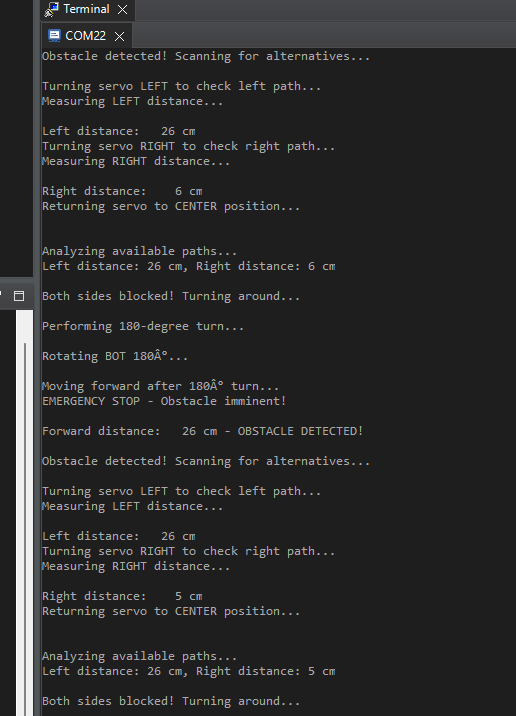
Figure 12: Logs-1
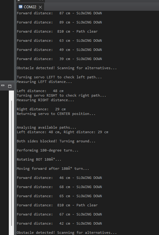
Figure 13: Logs-2
6.4 State Machine Implementation
The robot’s behavior is implemented using a state machine approach with the following states:
typedef enum {
STATE_INIT, // Initialize the system
STATE_IDLE, // Waiting for button press
STATE_MOVE_FORWARD, // Moving forward
STATE_SLOWING_DOWN, // Gradually slowing down
STATE_OBSTACLE_DETECTED, // Obstacle detected, need to scan
STATE_TURN_LEFT, // Turning servo to the left
STATE_MEASURE_LEFT, // Measuring distance to the left
STATE_TURN_RIGHT, // Turning servo to the right
STATE_MEASURE_RIGHT, // Measuring distance to the right
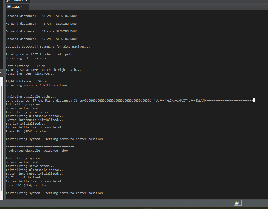
Figure 14: Logs-3
STATE_RETURN_CENTER, // Returning servo to center
STATE_DECISION, // Deciding which way to turn
STATE_ROTATE_BOT_LEFT, // Rotating the bot to the left
STATE_ROTATE_BOT_RIGHT, // Rotating the bot to the right
STATE_ROTATE_BOT_180, // Rotating the bot 180 degrees
STATE_PAUSED // System paused
} ProgramState;
Transitions between states are triggered by:
• Button presses (SW1, SW2)
• Obstacle detection (ultrasonic sensor readings)
• Completion of measurement/movement actions
The state machine is executed in the main loop with appropriate delays to control timing.
6.5 Timer Implementation
The system includes a timer module that provides:
• Countdown functionality for timed operations
• State tracking (IDLE, RUNNING, PAUSED)
• Functions for setting, starting, stopping, and updating the timer
• Integration with the display for showing the current time
The timer is updated through the SysTick interrupt handler and can control the robot’s operation time.
6.6 System Architecture
The obstacle avoidance robot integrates multiple components:
• Ultrasonic sensor for distance measurement
• Servo motor for scanning the environment
• Dual motors for movement control
• LEDs for status indication
• UART for debugging and status output
6.7 Obstacle Detection and Avoidance
The obstacle detection and avoidance algorithm follows these steps:
1. While moving forward, continuously measure the distance to obstacles using the ultrasonic sensor
2. If distance falls below SLOWDOWN THRESHOLD (100cm), begin reducing speed proportionally
3. If distance falls below OBSTACLE THRESHOLD (35cm), stop and enter obstacle detection mode
4. Scan left and right by rotating the servo and measuring distances
5. Choose the direction with more space:
• If both directions have sufficient space (¿ OBSTACLE THRESHOLD), choose the direction with more space
• If both directions are blocked, perform a 180° turn
6. Execute the chosen rotation and resume forward movement
The implementation includes special handling for critical situations:
• Emergency stopping for imminent collisions
• Progressive braking as obstacles get closer
• Different LED indications for various states
6.8 Motor Control Strategy
The motor control implementation uses a software PWM approach for speed contro1. A PWM signal is generated through the SysTick interrupt handler
2. The duty cycle is determined by the current speed variable (0–100%)
3. Direction is controlled through the IN1–IN4 pins of the motor driver
Special motor control features include:
• Dynamic braking through reverse motion (motors brake reverse)
• Emergency stopping (motors emergency stop)
• Speed calculation based on distance to obstacles
• Speed ramping during acceleration/decelerationl:
VII TECHNICAL CHALLENGES AND SOLUTIONS
Several technical challenges and their solutions are evident in the implementation:
1. Ultrasonic Sensor Timing:
• Challenge: Precise timing measurement for echo pulses
• Solution: Using hardware timer and edge-triggered interrupts for accurate time-of-flight calculation
2. Motor Speed Control:
• Challenge: Smooth speed control without hardware PWM
• Solution: Software PWM implementation through SysTick interrupts
3. Keypad Debouncing:
• Challenge: Reliable key detection without false triggers
• Solution: Debounce delays and state checking to filter mechanical bounce
4. State Management:
• Challenge: Complex robot behavior with multiple states
• Solution: Well-structured state machine with clear transitions
5. Obstacle Avoidance Logic:
• Challenge: Making intelligent decisions about navigation
• Solution: Scanning environment in multiple directions and choosing optimal path
VIII CONCLUSION
The TM4C123G-based embedded system demonstrates a comprehensive implementation of an obstacle avoidance robot with
multiple peripheral interfaces. The system showcases good embedded software practices:
• Modular design with clear separation of concerns
• Structured state machine for behavior control
• Effective use of interrupts for time-critical operations
• Systematic GPIO configuration and management
• Comprehensive error handling and safety features
The implementation provides a solid foundation for educational purposes, demonstrating fundamental concepts in embedded systems programming, real-time control, and autonomous robotics. The code structure also allows for easy extension with additional features such as mapping, path planning, or advanced sensor integration.
IX REFERENCES
[1] TM4C123GH6PM Datasheet – Texas Instruments
[2] EduARM4 Trainer Board Documentation
[3] HD44780 LCD Controller Datasheet
[4] HC-SR04 Ultrasonic Sensor Datasheet
[5] SG90 Servo Motor Datasheet
X OBSTACLE DETECTION AND AVOIDANCE ROBOTS
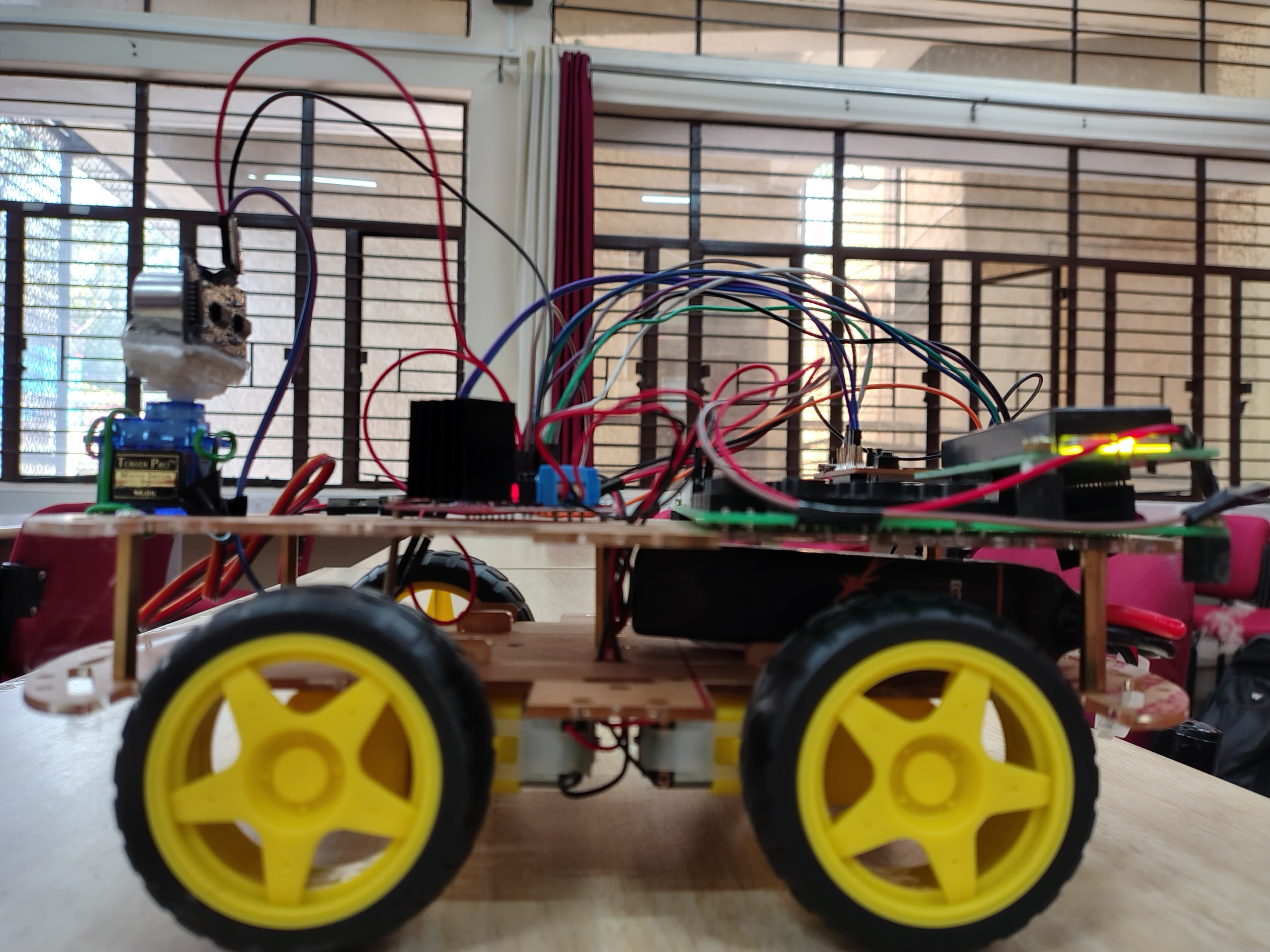
Figure 15: Bot Image – 1
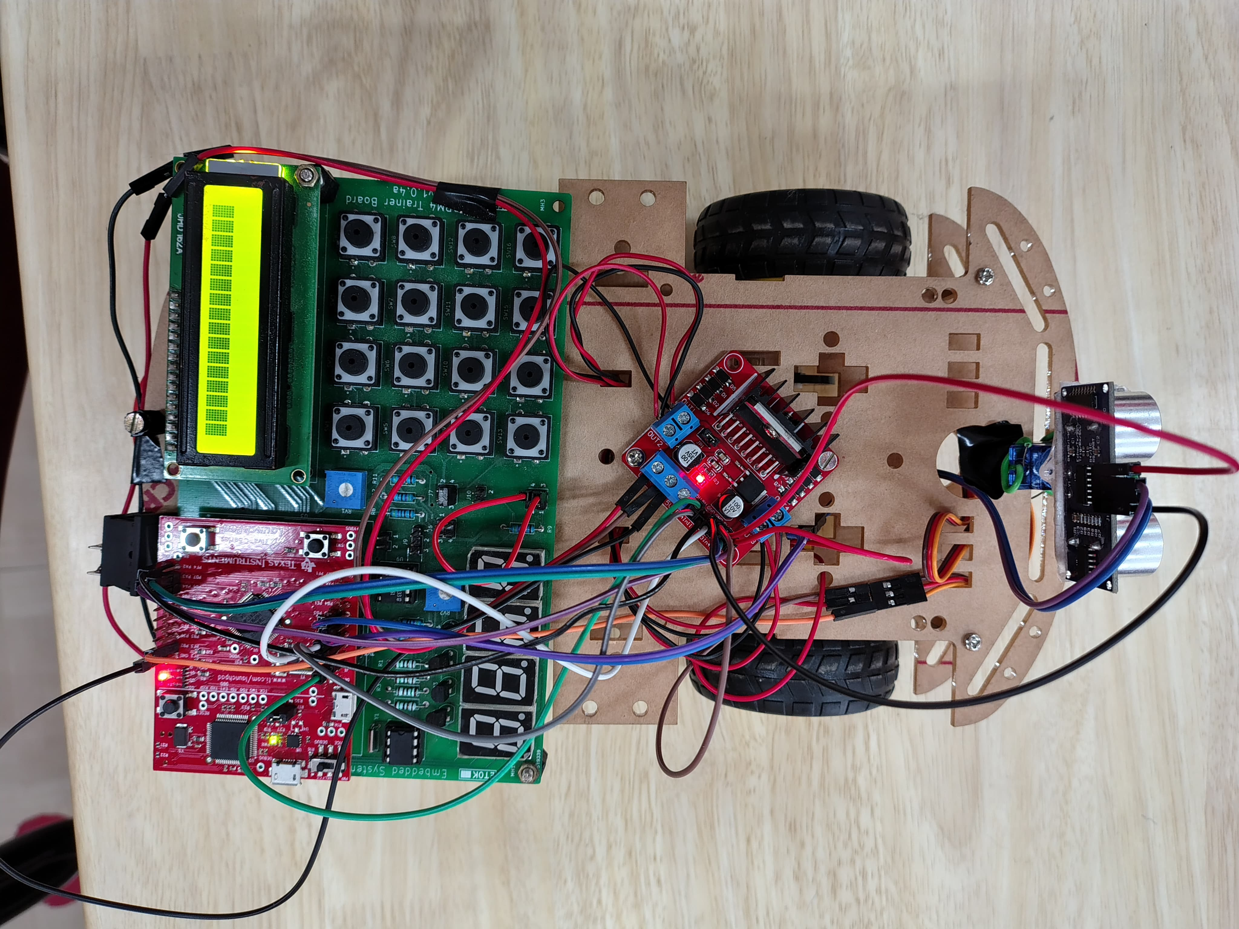
Figure 16: Bot Image – 2
Recent Comments