
I.PERMANENT MAGNET DC MOTOR
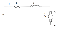
Figure 1: Permanent Magnet DC Motor
V=IR+Eb……(1)
where:
Eb is the back EMF
Ris the armature resistance
Eb ∝ω
Eb can be written as:
Eb=KEω……(2)
where:
KE is the back EMF constant
Substituting (2) in (1):
V=IR+KEω
ω=V−IR/KE …(3)
From (3), for a speed control omega here, the only parameter that can be controlled is the V .There is an applied voltage, armature voltage.
II.TORQUE SPEED CHARACTERISTIC
P=EbI….(4)
P=KEωI….(5)
where:
P is the power generated in the machine
Note: Power generated is not the product of V and I due to the losses in the resistor.
P=Tω….(6)
where:
T is the torque
Equating (5) and (6)
T=KtI…..(7)
Since for a machine Kt is constant, the torque is proportional to input armature current. So to vary the torque, variable armature current will have to be supplied. Hence to increase torque current will have to be increased and to decrease it current will have to be decreased.
I= T/Kt…(8)
Thus,
ω= V/KE- TR/KEKt….(9)
From equations (3) and (9) for maximum speed , T is 0 or I is zero i.e under no load conditions. Under such conditions V=Eb.
Thus,
ωmax= V/KE
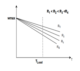
Figure 2: Torque Speed Characteristics
Plotting the torque speed characteristic for a particular V. As I increases speed will slowly decrease from the maximum speed. The rate of decrease depends on
R. Torque demanded by the load depends on armature current.
Now if the resistance R is increased the drop will increase. So by varying the armature resistance the speed can be varied. With increase in resistance the
speed decreases.
In the above graph
R1 <R2 <R3<R4
However this type of speed control system, does not give good dynamic performance. Since it is done manually it is a slow system. In a modern electric drive, it is frequently necessary to stop the drive work quickly accelerate or reverse it. Also four quadrant operation becomes necessary.
III.FOUR QUADRANT OPERATION OF DCMOTOR
To achieve efficient motor control, acceleration, deceleration, and speed reversal must be enabled in a controlled manner.
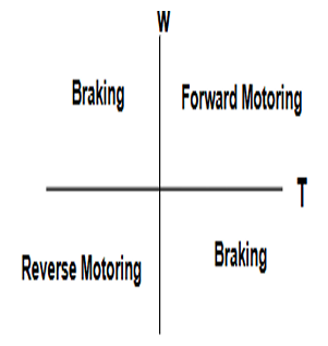
Figure 3: Four Quadrant Operation of DC Motor
1. Forward Motoring (First Quadrant):
• The motor runs in the forward direction with positive torque and positive speed.
• This is the standard driving mode where electrical energy is converted into mechanical motion.
2.Forward Braking (Second Quadrant):
- The speed remains positive, but the torque is negative, meaning a reverse torque is applied.
- This is required to decelerate the motor and return kinetic energy back to the power source.
3. Reverse Motoring (Third Quadrant):
• Both torque and speed are negative, meaning the motor runs in the reverse direction while still consuming power.
• This is similar to forward motoring but in the opposite direction.
4. Reverse Braking (Fourth Quadrant):
• The speed is negative, but the torque is positive, meaning the motor is braking in the reverse direction.
• This returns energy to the supply, similar to forward braking.
Since power is the product of torque and speed,
• In motoring modes, power is positive.
• In braking modes, power is either dissipated or regenerated back into the system.
IV.SPEED CONTROL USING ARMATURE VOLATGE
In PMDC motors, speed control is achieved solely by adjusting the armature voltage, since the flux is constant due to permanent magnets.
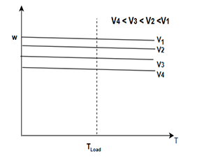
Figure 4: Torque Speed Characteristics with Varying Armature Voltage
From equation (9),
• By reducing the voltage (V), the motor speed decreases, leading to a family of parallel speed torque curves.
• Fine control of speed is achieved by continuously adjusting the applied voltage.
• In the above graph
V1 >V2 >V3 >V4
V.PRACTICAL IMPLEMENTATION
• Traditional speed control using variable armature resistance is inefficient due to increased losses.
• Instead, modern drives use phase-controlled converters (thyristors) to provide rapid and precise voltage control.
• This ensures efficient speed variation without unnecessary power dissipation.
• Since the flux is fixed by the permanent magnets in PMDC motors, voltage control is the only practical means for varying speed.
Thus, by carefully controlling the applied armature voltage, we can achieve smooth and efficient motor operation across all four quadrants.
VI.BRAKING METHODS AND DYNAMIC SPEED CONTROL
To decelerate a rotating machine, the kinetic energy must be extracted efficiently. This energy must either be returned to the source or dissipated. A suitable front-end converter should be capable of handling bidirectional power flow.
6.1 Types of Braking
There are three main braking techniques:
1. Regenerative Braking: Kinetic energy is converted to electrical energy and fed back to the power source. The front-end AC-DC converter (such as a PWM converter) must support bidirectional power flow.
2. Dynamic Braking: Instead of regenerating power, energy is dissipated in a resistor. The armature is disconnected from the supply and switched to a resistor, causing gradual deceleration.
In dynamic braking:
• The field winding remains unchanged, while the back emf (Eb) still exists due to inertia.
• The supply voltage is reduced until V < Eb, making the armature current fall to zero.
• A resistor is then connected to allow Eb to drive current through it.
The current equation becomes:
−I = Eb/R, where R ≫Ra (10)
T =KφI=−Kφ(Eb/R) (11)
As the speed reduces, the braking torque also reduces, ensuring smooth deceleration.
For all dynamic performances, regenerative braking is used mostly.
6.2 Speed Control and Constant Power Operation
Unlike separately excited DC motors, PMDC motors cannot operate in the constant power region through flux weakening, as the flux is fixed by the magnets. Therefore, the maximum achievable speed is limited by the applied voltage.
VII PRACTICAL IMPLEMENTATION
• Traditional speed control using variable armature resistance is inefficient due to increased losses.
• Instead, modern drives use phase-controlled converters (thyristors) to provide rapid and precise voltage control.
• This ensures efficient speed variation without unnecessary power dissipation.
Thus, by carefully controlling the applied armature voltage, we can achieve smooth and efficient motor operation across all four quadrants.
VIII H-BRIDGE BASED BIDIRECTIONAL MOTOR CONTROL
In practical PMDC motor drive systems, bidirectional control is commonly achieved using an H-bridge circuit. The L298 driver is a widely used integrated dual H-bridge motor driver capable of controlling the direction and speed of DC motors.
8.1 Principle of Operation
An H-bridge allows voltage to be applied across a load (the motor) in either direction. The L298 contains two full H-bridge circuits, enabling it to control two independent DC motors or a single motor with full four quadrant operation.
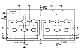
Figure 5: H-Bridge Configuration inside L298 (from datasheet)
8.2 Speed and Direction Control
The L298 allows for:
• Speed Control: By applying a PWM signal to the Enable pin, the effective voltage seen by the motor is varied, controlling its speed.
• Direction Control: By configuring the logic levels of the two Input pins (IN1, IN2), the direction of current through the motor can be reversed.
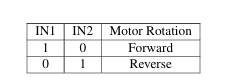
Table 1: Motor Direction and Braking Modes using L298
8.3 Braking Modes
The L298 also allows for basic braking techniques:
• Regenerative Braking: When both inputs are high (1,1), the motor terminals are shorted through the low-side switches, enabling energy to be dissipated or partially recovered if circuitry allows.
• Dynamic Braking: Achieved by shorting the motor terminals briefly; this can also be implemented in software via PWM patterns.
8.4 Advantages over Thyristor-Based Dual Converter
Compared to classical dual thyristor converters:
• The L298 provides fast electronic switching with no mechanical components.
• It’s suitable for low-voltage PMDC motors and embedded systems.
• PWM and direction control are handled by simple GPIO signals from a microcontroller.
Thus, for modern PMDC motor drives in robotics, EVs, and automation, H-bridge drivers like the L298 offer an efficient, compact, and low-cost solution for four-quadrant operation.
IX.DCMOTORSPEEDCONTROL

Figure 6: Block Diagram of DC Motor Speed Control
The speed reference and speed feedback are compared and passed through a controller. The output of the controller is used to generate a PWM signal. This PWM signal is fed to an H-bridge driver (such as L298), which applies a variable average DC voltage across the motor terminals. The motor has a tachometer to sense the speed. The ripple in tachometer output is filtered out and gain is changed to bring it down to the controller level using a speed filter.
9.1 MOTOR MODEL
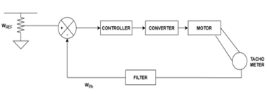
Figure 7: Motor Model
VA =IARA+LA (dIA/dt) +Eb (12)
where:
- VA is the effective armature voltage (volts), obtained as the average value of PWM applied via the L298 driver.
- IA is the armature current (amperes).
- RA is the armature resistance (ohms).
- LA is the armature inductance (Henrys).
Eb is the back EMF(volts),which depends on motor speed.
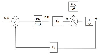
Figure8:Final PMDC Motor Model
In PWM-based motor control systems such as those using the L298 driver, the controller outputs a duty cycle signal which modulates the supply voltage applied
to the motor. When the motor is at standstill and a high, speed command is given, the controller quickly outputs a high duty cycle, resulting in nearly full supply voltage applied through the H-bridge, there by initiating rapid acceleration.
X.NECESSITY OF A CURRENT CONTROL LOOP
In an induction machine, speed is proportional to armature voltage. At standstill, when full voltage is applied, there is no back EMF. From the governing equation for armature voltage Va, armature current Ia, and back EMF Eb, it follows that in the absence of back EMF, the applied voltage is dropped across the armature resistance and leakage inductance.
This results in a high in rush current at startup. Depending on the applied voltage, the current may exceed the rated value of the machine. Until the machine gains speed, the excessive current can cause overheating of
the windings, potentially leading to damage.
A proper speed control system must not only regulate speed and voltage but also ensure that the motor does not exceed its current rating. Machines have de
fined voltage and current limits, including a maximum permissible current rating for safe operation. Any violation of these limits can result in thermal and electrical
stress on the machine.
To mitigate this issue, a current control loop is required. The applied voltage Va must be regulated based on the real-time current drawn by the motor. This en sures that during acceleration, deceleration, or torque variations, the machine does not draw excessive current.
The current loop must operate at a much faster timescale compared to mechanical speed variations, which are dictated by the mechanical time constant.
The block diagram of the system must be modified to include this inner current control loop, and the controller must be designed accordingly to regulate both
voltage and current effectively.
XI.DESIGN OF THE COMPLETE SPEED CONTROL SYSTEM
The armature voltage VA(s) must be controlled according to the current in the motor. A reference current IA(s)ref is introduced, defining the maximum and min
imum current limits for positive and negative torque based on the motor’s rating.
A current feedback loop is required to compare the actual current IA(s) with the reference IA(s)ref. A controller ensures that if the current exceeds the rated
value, the armature voltage is adjusted to maintain safe operating conditions.
The motor model can be represented as:
(1/RA)/(1+sTA)
where RA is the armature resistance, and TA is the electrical time constant. A feedback filter is necessary to remove switching ripple and ensure smooth DC current measurement.
The current control loop must regulate VA dynamically to achieve maximum positive and negative torque within the current rating. The speed controller out
put now regulates IA(s) instead of directly controlling VA(s). This intermediate step ensures that the system provides the correct torque T = KtIA, where Kt is the torque constant.
The complete closed-loop diagram will be formulated, and the controllers will be designed to regulate both speed and current effectively. The system will be
implemented on hardware to analyze its response.
XII.SYSTEM ARCHITECTURE
12.1 Key Components
1. TM4C123GH6PM Microcontroller
• Texas Instruments ARM Cortex-M4F based MCU running at 16MHz
• Provides PWM generation, ADC inputs, and quadrature encoder interface
2. L298N Motor Driver
•H-bridge motor driver capable of bidirectional control
•Accepts PWM input (ENA pin)for speed control
• IN1/IN2 inputs for direction control
• Capable of driving motors at up to 2A continuous current
3. AMT103 Quadrature Encoder
• 2048 Pulses Per Revolution(PPR) for high resolution feedback
• Provides A and B phase outputs with 90◦ phase difference
• Includes index signal(X) for absolute position reference
• 5V power supply with digital outputs
4. ACS712 Current Sensor(5A)
- Hall-effect based current sensor with 185mV/A sensitivity
- Provides analog output proportional to motor current
- Bidirectional current sensing capability
12.2 System Block Diagram
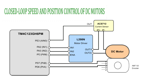
Figure 9: Block diagram of the closed-loop DC motor control system
XIII.CONTROL SYSTEM IMPLEMENTATION
13.1 Control Architecture
The control system consists of three cascaded control loops:
1. Inner Loop (Current Control)
• PI controller with Kp = 5.0, Ki = 0.8
• Directly controls PWM duty cycle
• Anti-windup protection for integral term
2. Speed Control
• PI controller with Kp = 0.1, Ki = 0.5
• Outputs current reference to inner loop
• Anti-windup protection for integral term
13.2 Signal Conditioning
13.2.1 Current Measurement
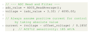
To obtain an accurate and stable current measurement, the following techniques are employed:
• ADC Averaging: 64 samples are averaged to suppress high-frequency noise.
• Offset Calibration: The zero-current voltage (offset_voltage) is measured during system initialization. It was foud to be 1.65V.
• Current Conversion: The sensor output is converted to current using the ACS712 sensitivity of 185 mV/A.
13.2.2 Speed Measurement
Accurate speed measurement is critical for the proper functioning of the closed-loop control system. The implemented solution uses the TM4C123GH6PM’s
Quadrature Encoder Interface (QEI) peripheral to measure both the position and speed of the motor with high precision.
Speed measurement is implemented in the QEI0_GetRPM() function, which converts raw encoder data into rotational speed in revolutions per minute (RPM). The algorithm employs several techniques to ensure accurate and noise-resistant measurements:
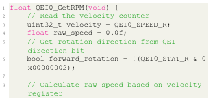
Listing 1: Speed measurement implementation
The speed measurement process involves the following key aspects:
1. Primary Velocity Measurement: The QEI peripheral’s velocity register (QEI0_SPEED_R) provides a count of encoder pulses within a fixed time window.
2. Direction Detection: The rotation direction is determined by reading the direction bit from the QEI status register (QEI0_STAT_R), where bit 1 indi
cates reverse rotation when set.
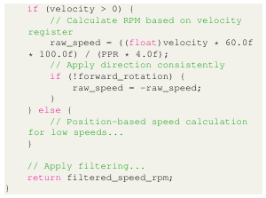
3. Conversion to RPM: The raw velocity count is converted to RPM using the formula:
RPM=velocity count×60×sampling frequency / PPR×4
Where:
• velocity count is the number of encoder edges detected
• 60 converts from revolutions per second to revolutions per minute
• sampling frequencyis100Hz (period of 10ms)
• PPR is the encoder’s pulses per revolution (1000)
• 4 accounts for the quadrature encoding (4 counts per pulse)
4. Sign Application: The calculated speed magnitude is given the appropriate sign based on the detected rotation direction.
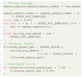
To ensure stable speed readings in the presence of noise and mechanical imperfections, the raw speed values undergo a three-stage filtering process:
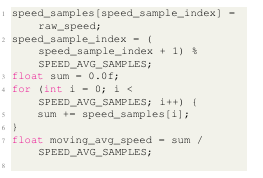
(a) Moving Average Filter: The last 15 speed samples are averaged to reduce random variations:
(b) Low-Pass Filter: An exponential low-pass filter further smooths the moving average result:
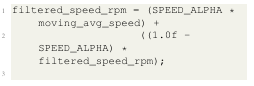
Where SPEED_ALPHA (0.05) is the filter coefficient determining the balance between responsiveness and smoothing.
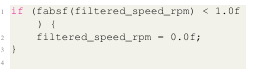
(c) Dead-Band Filter: Very small speed values (below 1 RPM)are treated as zero to prevent noise near standstill:
XIV.HARDWARE CONFIGURATION AND SETUP
14.1 Microcontroller Configuration
14.1.1 Clock Configuration
• System clock: 16MHz
• Peripheral clocks enabled for ADC, PWM, QEI, GPIO
14.1.2 PWM Configuration
• PWM frequency: ∼8kHz
• 1000-step resolution
• Module 1, Generator 3, Output 6 (M1PWM6)
14.1.3 QEI Configuration
• Quadrature phase mode (both edges of both channels)
• 4xresolution multiplication (4 * 2048 PPR = 8192 counts/revolution)
• Velocity capture enabled with 10ms sampling window.
14.1.4 ADC Configuration
• 12-bit resolution
• Sample sequencer 3 used
• Hardware averaging (16x) enabled
• Sampling triggered by software
14.2 L298N Motor Driver Setup
14.2.1 Connection Details
• IN1/IN2: Direction control inputs
• ENA: PWM input for speed control
• OUT1/OUT2: Motor connections
• Power supply: Separate logic (5V) and motor (12V) supplies
14.2.2 Operating Characteristics
• Logic level: 5V
• Motor voltage: 12V
• Max continuous current: 2A
14.3 AMT103Encoder Installation
14.3.1 Electrical Connection
• 5Vpower supply
• A and B channels connected to QEI inputs
• Ground connection to system ground
• Optional index (X) channel for position reference
XV.SOFTWARE IMPLEMENTATION HIGHLIGHTS
15.1 Initialization Sequence
1. Configure system clock and enable peripheral clocks
2. Initialize GPIO pins for L298N control
3. Configure PWM module for motor control
4. Set up QEI module for encoder feedback
5. Initialize ADC for current sensing
6. Calibrate current sensor offset
7. Initialize control loop variables and parameters
15.2 Control Loop Implementation
The main control loop implements a cascaded controller with:
1. ADC sampling for current measurement with filtering
2. QEI reading for speed measurement with multi stage filtering
3. Direction control based on speed reference sign
4. PWM duty cycle control for motor power regulation
15.3 Filtering and Signal Processing
15.3.1 Current Filtering
![]()
With ALPHA set to 0.1, this equation implements an exponential moving average where 0.1 of the new measurement is combined with 0.9 of the previous
filtered value. This creates a smoothing effect that reduces noise while preserving slower trends in the data. Reducing alpha reduces fluctuations in measurement but slows down the response time.
15.3.2 Speed Filtering
For the speed loop, 3 filters have been implemented:
- It calculates a moving average by storing raw speed values in a circular buffer and averaging them, which reduces random fluctuations.
- It applies a low-pass filter (with SPEED=0.05 as the coefficient) that blends the moving average with previous filtered values, further smoothing the signal while preserving longer-term trends.
- It implements a dead-band filter that eliminates very small speed values (below 1.0 RPM), preventing noise from being interpreted as minimal movement when the system is actually stationary.
15.3.3 Direction Control
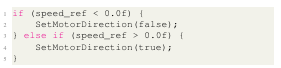
If the reference speed (speed) is negative, it sets the motor direction to reverse (false). If the reference speed is positive, it sets the motor direction to forward (true). This ensures the motor rotates in the correct direction based on the sign of the commanded speed.
XVI.WEBINTERFACE FOR DC MOTOR CONTROL AND MONITORING
The DC motor control system incorporates a web based monitoring and control interface implemented using Python Flask. This interface enables real-time visualization of motor performance and interactive control capabilities.
16.1 Communication Protocol
The microcontroller communicates with the monitoring application using UART at 115200 bps. The system uses a text-based protocol with the following message formats:
• Speed data: REF SPEED:< ref_speed >, ACT SPEED:< actual_speed >%
• Current data: CURRENT:< ref_current >mA, ACTUAL: < actual_current>mA
Commands sent to the microcontroller follow a simple syntax:
• set speed < value >-Sets speed reference( -4500 to 4500 RPM)
• angle < value > – Sets position reference (0-359 degrees)
16.2 Web Interface Features
The monitoring system provides multiple specialized dashboards:
-
- Speed Monitor: Real-time plotting of reference and actual speed
- Current Monitor: Visualization of current con troller performance

Figure 10: Web-based motor control interface
• Position Control: Interactive motor position adjustment
• UART Monitor: Raw data visualization and logging
The system implements these features using:
• A dedicated background thread for non-blocking UART communication
• Thread synchronization to prevent race conditions
• Real-time data visualization using Plotly.js
• Interactive simulations that demonstrate practical applications
This monitoring system enhances the motor control project by providing intuitive visualization and control capabilities, making it an effective tool for both development and educational purposes.
XVII.EXPERIMENTAL RESULT
17.1 Speed Control Performance
One of the key performance metrics for a closed-loop control system is its step response, which indicates how quickly and accurately the system can respond to changes in the reference input.
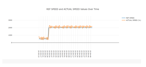
Figure 11: Step response of the motor speed control system showing reference speed (blue) and actual speed (orange)
Recent Comments