
I.Introduction
Maintaining firmware in embedded systems poses significant challenges, particularly in safety-critical applications where system downtime or unexpected behavior can have severe consequences. This challenge is amplified in sealed or inaccessible enclosures where physical access is impractical.
This project addresses these challenges through a dual-application bootloader architecture designed for TM4C123GH6PM microcontrollers. The system provides:
• Reliable remote firmware updates via UART/XMODEM
• Dual-application architecture for resilience
• State-preserving fallback mechanism for operational continuity
• Real-time plant safety monitoring
• Comprehensive error detection and recovery
A unique aspect of this implementation is that even during application failure, the system can preserve its operational state and continue processing from the point of failure after recovery, ensuring minimal disruption to the overall system functionality.
II. System Architecture
2.1 Hardware Components
The system consists of two TM4C123GH6PM microcontroller boards:
• Controller Board: Executes the bootloader and applications, and handles firmware updates.
• Feedback Board: Generates a 1 pulse-per-second (1PPS) safety signal and monitors vibration.
These boards communicate through a direct GPIO connection (PB0), where the 1PPS signal from the Feedback Board serves as a safety heartbeat for the Controller Board. The Controller Board connects to a PC via UART for firmware update and monitoring purposes.
2.2 Software Architecture
The software architecture consists of three primary components:
• Bootloader: Manages flash memory, validates applications, handles firmware updates, and orchestrates application switching based on validation and error conditions.
• Application 1 (Fallback): Provides reliable operation focused on completing critical tasks even without external signals. It can resume operation from the last known state of Application 2 if a failure occurs.
• Application 2 (Active): The primary high-performance application that monitors the 1PPS signal for plant safety, processes state transitions, and performs the main system functions.
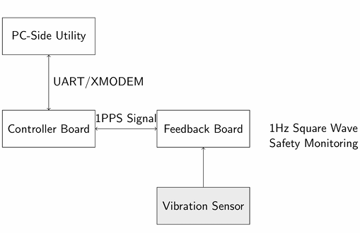
Figure 1: System Architecture Diagram
2.3 Memory Layout
The system utilizes a carefully structured flash memory layout to support the dual-application architecture:
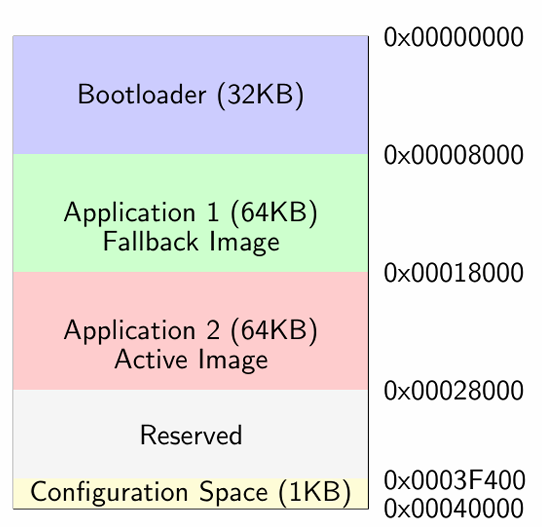
Figure 2: Flash Memory Layout
The TM4C123GH6PM flash memory (256KB) is divided into several distinct regions:
• Bootloader (0x00000000- 0x00007FFF): 32KB for bootloader code
• Application 1 (0x00008000- 0x00017FFF): 64KB for fallback application
• Application 2 (0x00018000- 0x00027FFF): 64KB for active application
• Reserved (0x00028000- 0x0003F3FF): Reserved space
• Configuration (0x0003F400- 0x0003FFFF): Configuration space for application information and error handling
2.4 Configuration Space
The configuration space at the end of flash memory stores critical system information:
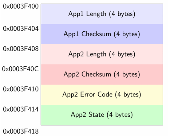
Figure 3: Configuration Space Layout
The configuration space contains:
• App1 Length (0x0003F400): Size of Application 1 in bytes
• App1 Checksum (0x0003F404): CRC-32 checksum of Application 1
• App2 Length (0x0003F408): Size of Application 2 in bytes
• App2 Checksum (0x0003F40C): CRC-32 checksum of Application 2
• App2 Error Code (0x0003F410): Error code if Application 2 fails
• App2 State (0x0003F414): Last state of Application 2 before failure
This configuration space enables the bootloader to validate applications, track errors, and preserve state information between application failures and recoveries.
III Bootloader Implementation
The bootloader serves as the foundation of the system, managing application validation, selection, and firmware updates.
3.1 Boot Sequence
The bootloader’s operation follows a well-defined sequence:
1. System initialization (GPIO, UART, SysTick timer)
2. Display menu with 5-second timeout
3. Check for App2 error code in configuration space
4. If no errors, validate App2 using CRC-32 checksum
5. If App2 is valid, jump to App2 (normal path)
6. If App2 has errors or fails validation, validate App1
7. If App1 is valid, clear App2 error code and jump to App1 (fallback path)
8. If no valid applications exist, remain in bootloader and prompt for new firmware
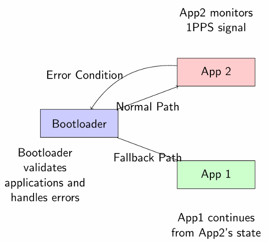
Figure 4: Boot Flow Diagram
3.2 Application Validation
The bootloader performs thorough validation of applications before execution:
1. Verify stack pointer is within RAM bounds (0x20000000- 0x20008000)
2. Verify reset vector points to a valid location in application flash
3. Read application length and stored CRC-32 checksum from configuration
4. Calculate CRC-32 checksum of application binary in flash
5. Compare calculated checksum with the stored checksum
6. Only execute the application if all validation steps pass
This validation ensures that only properly programmed and uncorrupted applications are executed.
3.3 Firmware Update Process
The bootloader provides a menu-driven interface for firmware updates:
1. User selects to update either Application 1 or Application 2
2. Bootloader initiates XMODEM transfer via UART
3. Received data is stored in a RAM buffer
4. Buffer contents are programmed to appropriate flash memory location
5. CRC-32 checksum is calculated for the new application
6. Application length and checksum are stored in configuration space
7. System confirmation is provided through status LEDs and UART messages
3.4 Flash Memory Management
The bootloader implements robust flash memory operations:
• Sector-Based Erase: Flash memory is erased in 1KB sectors
• Word-Aligned Writes: Data is written as 32-bit words at word-aligned addresses
• Verification: Each write operation is verified to ensure data integrity
• Interrupt Management: Interrupts are disabled during flash operations
• Error Handling: Timeouts and verification failures are detected and reported
This flash memory management ensures reliable firmware updates and configuration storage.
3.5 Configuration Management
The bootloader maintains critical system information in the configuration space:
• Updates application information during firmware updates
• Preserves unrelated configuration when updating a single application
• Handles error code detection and clearing
• Manages state preservation for application continuity
The configuration management system ensures that applications can be updated independently while maintaining
system integrity.
IV.XMODEM Protocol Implementation
The XMODEM protocol facilitates reliable firmware transfers between the PC and the microcontroller.
4.1 Protocol Overview
XMODEM is a simple file transfer protocol with error detection capabilities:
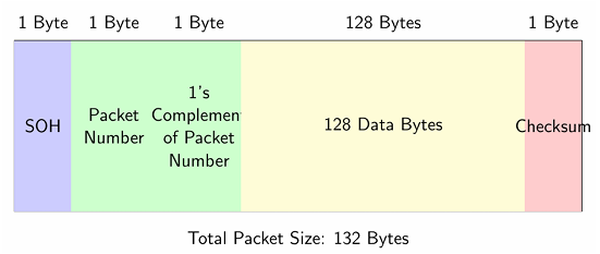
Figure 5: XMODEM Packet Structure
• Packet Format: SOH (0x01) + Packet Number + 1’s Complement of Packet Number + 128 Data Bytes +Checksum
• ACK/NAK: Simple handshaking mechanism for acknowledgment or retransmission
• EOT: End of Transmission marker
• Error Detection: Checksum and packet number verification
4.2 XMODEM Transfer Flow
The XMODEM transfer follows a specific sequence:
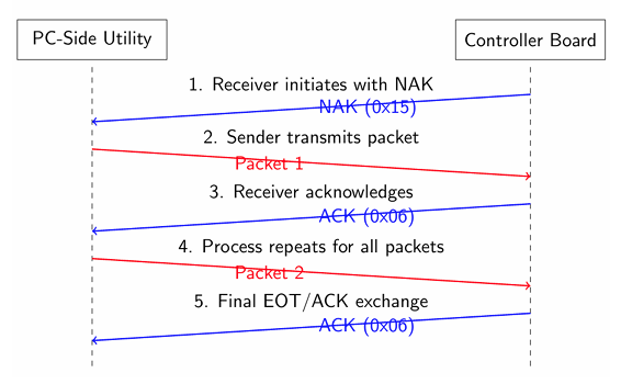
Figure 6: XMODEM Transfer Flow
1. Receiver initiates with NAK (0x15)
2. Sender transmits packet (SOH + Packet Number + 1s Complement of Packet Number + 128 data bytes + Checksum)
3. Receiver verifies packet integrity using checksum and packet number
4. Receiver sends ACK (0x06) if packet is valid, or NAK if invalid
5. Sender transmits next packet or retransmits on NAK
6. Process repeats until all data is transferred
7. Sender transmits EOT (0x04) to indicate end of transmission
8. Receiver acknowledges with ACK to complete the transfer
4.3 Implementation Details
The XMODEM implementation includes robust error handling and timeout management:
• Timeout Management: Timeouts for packet reception and acknowledgment
• Retry Mechanism: Multiple retry attempts for failed transmissions
• Buffer Management: RAM buffer for received data
• Packet Validation: Comprehensive packet integrity checking
• Cancellation Handling: Ability to cancel transfer (CAN character)
V. Application Design
The system implements two applications with distinct responsibilities and behaviors.
5.1 Application 2 (Active)
Application 2 serves as the primary high-performance application with safety monitoring capabilities:
• 1PPS Monitoring: Continuously monitors the 1PPS signal from the Feedback Board
• State-based Operation: Implements a 5-state operation cycle with 10-second intervals
• Error Detection: Identifies signal loss (3+ seconds without pulse)
• Error Handling: Records current state and error code in flash
• System Reset: Triggers system reset to invoke bootloader recovery
• Visual Feedback: Provides status indication through RGB LEDs
5.2 Application 1 (Fallback)
Application 1 serves as the reliable fallback application with state-aware recovery:
• State Recovery: Reads App2’s last state from configuration
• Continuation Logic: Resumes processing from App2’s last state
• Conservative Operation: Operates without depending on external signals
• Task Completion: Ensures critical tasks are completed
• Visual Feedback: Indicates state and operation through LEDs
5.3 State-Preserving Fallback Mechanism
The state-preserving fallback mechanism ensures operational continuity:
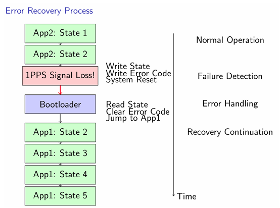
Figure 7: Error Recovery Process
1. App2 detects failure condition (1PPS signal loss)
2. Current state information is saved to configuration space
3. Error code is written to indicate the failure
4. System reset is triggered
5. Bootloader detects error and validates App1
6. App1 reads App2’s last state from configuration
7. App1 resumes processing from App2’s last state
8. Processing continues with minimal disruption
This mechanism enables the system to maintain operational integrity even when the primary application fails.
VI.Feedback Board Implementation
The Feedback Board generates the 1PPS signal and monitors vibration to simulate a plant safety system.
6.1 1PPS Signal Generation
The board generates a 1Hz square wave serving as a safety heartbeat:
• Signal Format: 1Hz square wave (500ms high, 500ms low)
• GPIO Pin: PB0 used for 1PPS output
• Timer-Based: SysTick timer used for precise timing
6.2 Vibration Detection
The Feedback Board includes vibration detection functionality:
• Input Pin: PC4 used for vibration sensor input
• Interrupt-Driven: Edge-triggered interrupts for real-time detection
• Signal Control: Stops 1PPS output when vibration is detected
• Visual Indication: RGB LEDs indicate normal operation (green) or alarm condition (red)
VII.PC-Side Utility
A Windows-based PC utility facilitates user interaction with the system:
7.1 Utility Features
The PC-Side utility provides a comprehensive interface for system management:
• Serial Communication: Connects to the controller board via UART (9600 baud)
• Command Interface: Sends commands to the bootloader and applications
• XMODEM Implementation: Handles file transfers for firmware updates
• Terminal Emulation: Displays system output and status information
• File Selection: Allows selection of binary files for firmware update
7.2 User Interface
The utility offers a straightforward command-based interface:
1. Commands:
• 1- Flash Application 1 (Fallback Image)
• 2- Flash Application 2 (Active Image)
• 3- Proceed to application execution
• 4- Exit to bootloader menu
• h- Display help menu
• q- Quit application
2. XMODEM Transfer: Initiates when bootloader is ready for transfer
3. Status Display: Shows transfer progress and system responses
7.3 Implementation Details
The utility is implemented in C for Windows systems:
• Multithreaded: Separate threads for serial reading and keyboard input
• File Handling: Reads binary files for firmware transfer
• XMODEM Logic: Complete implementation of XMODEM protocol
• Error Handling: Detects and manages transfer failures
• User Guidance: Help menu and informative prompts
VIII.System Testing and Results
The system underwent comprehensive testing to validate its functionality and robustness.
8.1 Firmware Update Testing
Firmware update functionality was tested through multiple scenarios:
• Application 1 Update: Successfully uploaded and validated the fallback application
• Application 2 Update: Successfully uploaded and validated the active application
• Error Handling: Verified error detection during invalid transfers
• Timeout Management: Confirmed timeout handling during transfer interruptions
• Verification: Validated CRC-32 checksum verification of applications
8.2 State Preservation Testing
State preservation and recovery were tested through simulated failures:
• Failure Injection: Simulated 1PPS signal loss in different states
• State Recording: Verified state and error code storage in configuration
• Recovery Path: Confirmed bootloader switched to App1 after failure
• State Continuity: Verified App1 continued from App2’s last state
• Task Completion: Confirmed all state processing completed despite failures
8.3 Feedback Board Testing
The Feedback Board functionality was validated through various tests:
• 1PPS Signal: Verified stable 1Hz square wave generation
• Vibration Detection: Confirmed responsive vibration detection
• Signal Stoppage: Verified 1PPS signal stopped upon vibration detection
• Visual Indication: Confirmed LED status indicators accurately reflected system state
8.4 Key Results
The testing yielded the following key results:
• Firmware Update Reliability: 100% success rate for valid firmware files
• State Preservation Accuracy: 100% success in preserving and recovering state
• Failure Detection: 100% detection rate for 1PPS signal loss
• Recovery Time: Less than 1 second from failure to App1 execution
• System Continuity: No loss of critical tasks despite application failures
IX.Conclusion
This project successfully demonstrates a robust dual-application bootloader system with state-preserving fallback capabilities for TM4C123GH6PM microcontrollers. The implemented system addresses critical challenges in remote firmware updates for safety-critical systems where physical access is limited.
9.1 Key Achievements
The project showcases several significant achievements:
• A reliable bootloader with comprehensive application validation
• Secure remote firmware update mechanism using XMODEM protocol
• Innovative state-preserving fallback for operational continuity
• Real-time plant safety monitoring with vibration detection
• Structured flash memory management with configuration space
• Comprehensive error detection and recovery mechanisms
9.2 Real-World Applications
The system design is particularly suitable for several real-world applications:
• Industrial control systems in hazardous environments
• Remote monitoring stations in inaccessible locations
• Critical infrastructure systems requiring high reliability
• Safety-critical applications with fault-tolerance requirements
• IoT devices deployed in remote locations
• Sealed embedded systems requiring firmware maintenance
9.3 Future Enhancements
Several potential enhancements could further improve the system:
• Encryption: Adding encryption to the XMODEM protocol for secure updates
• Advanced Diagnostics: Enhanced error reporting and diagnostics
• Expanded State Management: More granular state preservation
• Wireless Connectivity: Adding wireless update capability
• Power Management: Implementing low-power modes for battery operation
• Expanded Sensor Suite: Additional safety monitoring sensors
This project demonstrates that embedded systems can achieve both updateability and high reliability through careful architecture design, robust validation mechanisms, and intelligent state management. By ensuring operational continuity even during failures, this approach offers a valuable solution for critical applications where downtime must be minimized while still enabling future firmware enhancements.
References
[1] Texas Instruments, “Tiva™ TM4C123GH6PM Microcontroller Datasheet,” April 2013.
[2] ARM, “Cortex-M4 Technical Reference Manual,” ARM Ltd, 2012.
[3] Ward Christensen, “XMODEM/YMODEM Protocol Reference,” 1986.
[4] IEEE, “IEEE 802.3 Standard for Ethernet,” Section 3.2.9, CRC-32 Algorithm.
[5] Jonathan Valvano, “Embedded Systems: Real-Time Operating Systems for ARM Cortex-M Microcontrollers,” 4th Edition, 2020.
Recent Comments