
I.OBJECTIVE
Develop a compact and programmable system capable of monitoring vehicle parameters, detecting faults through the OBD-II interface, and displaying real-time diagnostic information.
II.SYSTEM ARCHITECTURE
The system consists of a OBD Emulator and OBD Scanner, OBD Emulator is the module that is been built up with Python and TIVA to provide responses and emulate the car behavior, while the OBD scanner consists of TIVA along with Touch LCD to display the parameters and data. The Emulator and scanner communicates CAN with OBD protocol in application layer.
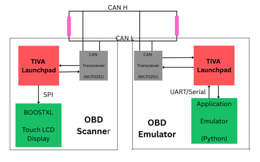
Figure 1: Complete system architecture showing (1) TIVA microcontroller with CAN interface, (2) Kentec QVGA touchscreen display,(3) Python emulator communication, and (4) Vehicle ECU connection via CAN Bus
III.DESIGN IMPLEMENTATION
3.1 Hardware Components
• TIVA TM4C123GH6PM microcontroller with CAN 2.0B controller
• MCP2551CANtransceiver implementing ISO 11898-2
• Kentec QVGA Booster Pack with SSD2119 controller (320×240 resistive touch)
3.2 Software Components
• Embedded firmware with OBD-II protocol stack (ISO15765-4)
• Python emulator using CustomTkinter and pyserial
• GRAM display driver with grlib graphics library
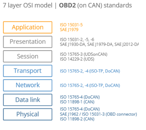
Figure 2: OBD-II protocol stack implementation showing physical layer (CAN), transport layer (ISO-TP), and application layer (OBD services)
IV.TECHNICAL SPECIFICATIONS
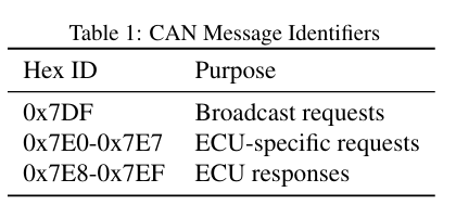
4.1 CAN Communication
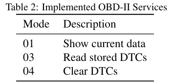
4.2 Diagnostic Services
4.3 Parameter Conversion
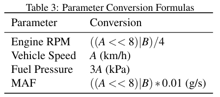
4.4 Packet Format
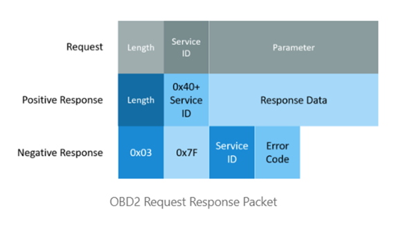
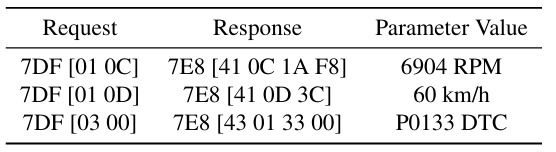
Figure 3: OBD Request and Response packet format over CAN
4.5 DTC format
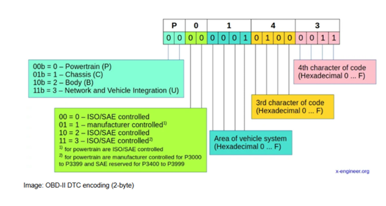
Figure 4: Diagnostic Trobule Code format encoding in 2 bytes
V.RESULTS
5.1 OBD Scanner
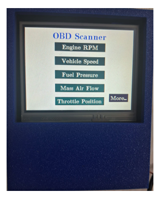
Figure 5: Display interface- showing list of PIDs available in the OBD module
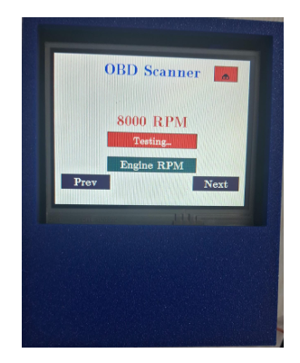
Figure 6: Mode 01- Showing real-time data for Engine RPM
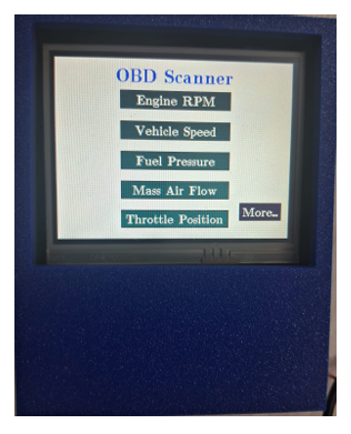
Figure 7: Display interface- showing list of PIDs available in the OBD module
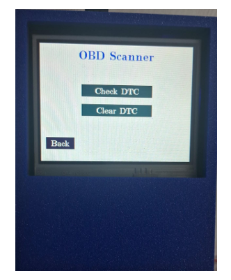
Figure 8: Mode 03 and 04 support buttons in OBD scanner
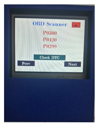
Figure 9: Display interface- Showing the stored DTCs in the ECU memory
5.2 Emulator results and Screens
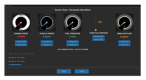
Figure 10: Python emulator interface showing Live data simulation along with CAN message monitoring
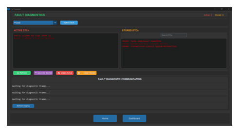
Figure 11: Python emulator interface showing Fault Management along with CAN message monitoring
5.3 Test Data
VI.CONCLUSIONS
The developed OBD-II diagnostic system has two components with the features achieved given below
6.1 OBD Scanner
• Real-time monitoring of 5+ vehicle parameters
• Complete DTC management (read/clear)
• Interactive touchscreen interface
• Accurate emulation of ECU responses
6.2 OBD Emulator
• User interactive car emulation software for 5 PIDs
• Enhanced Fault Management System creation that provides visualization how fault memory is managed in ECU.
• Complete plug and play interface with CAN capability.
• Modifiable and enhancable design software wise.
Recent Comments