
I.INTRODUCTION
The Dino Game implementation is a simplified version of the classic Chrome offline game, designed to run on an embedded system with a 320×240 LCD display, touch screen interface, and MPU6050 motion sensor. The game features a dinosaur character that runs automatically while the player controls jumping and crouching to avoid obstacles. Physics are simulated using gravity (-6.5f) and jump velocity (20.0f), with real-time position updates calculated through kinematic equations. Collision detection employs Axis-Aligned Bounding Box (AABB) for obstacles and circular detection for coins, with separate hitboxes for crouched and standing states.
Input is handled through both touch controls and motion sensing. The touch screen is divided into regions â touching the top half crouches, while the bottom half triggers jumps when the dino is grounded. Additionally, the MPU6050 accelerometer enables motion-based controls, where forward tilt (>5000) initiates a jump and backward tilt (<-5000) activates crouching. Obstacles are procedurally generated, including two types: cacti that must be jumped over and barriers that require crouching. The game progressively increases difficulty by speeding up obstacles as the score rises. Graphics are rendered using primitive shapes â rectangles for the dino and obstacles, circles for coins, and lines for the scrolling ground effect. Animation is frame-based, alternating between two leg positions for running and switching to a crouched sprite when needed. The game follows a state machine with menu, playing, and game-over states, tracking score and maintaining a high score. Performance optimizations include selective redraw techniques and a fixed-time step game loop synchronized with SysCtl Delay. The hardware integration involves the Kentec LCD with an SSD2119 controller, I2C communication for the MPU6050 sensor, and touch screen interrupts, demonstrating efficient embedded game development with limited resources.
II.COMMUNICATION PROTOCOLS
2.1 SPI (Serial Peripheral Interface)
SPI is a synchronous, full-duplex serial communication protocol characterized by:
• 4-Wire Interface:
- SCLK(Serial Clock)- Master-generated clock
- MOSI(Master Out Slave In)- Data from master to slave
- MISO(Master In Slave Out)- Data from slave to master
- SS/CS (Slave Select/Chip Select)- Slave selection line
• Key Features:
- Typical clock speeds: 1MHz to 50MHz (higher than I2C)
- Push-pull drivers provide better noise immunity
- Supports daisy-chaining with multiple slaves
- No addressing scheme- uses dedicated chip select lines
• Advantages:
- Higher data throughput (full-duplex)
- Simple hardware implementation
- Flexible data frame sizes
• Disadvantages:
- Requires more pins (4 minimum)
- No hardware acknowledgment
- No built-in collision detection
2.2 I2C (Inter-Integrated Circuit)
I2C is a synchronous, half-duplex multi-master protocol featuring:
• 2-Wire Interface:
- SCL(Serial Clock)- Bidirectional clock line
- SDA(Serial Data)- Bidirectional data line
• Key Features:
- Standard speeds: 100kHz (Standard), 400kHz (Fast), 1MHz (Fast+)
- 7-bit or 10-bit addressing scheme
- Open-drain configuration with pull-up resistors
- Built-in collision detection and arbitration
• Advantages:
- Minimal pin count (only 2 wires)
- Supports multiple masters and slaves
- Hardware acknowledgment (ACK/NACK)
- Well-suited for short-distance board-level communication
• Disadvantages:
- Lower speed compared to SPI
- More complex protocol handling
- Requires pull-up resistors
- Half-duplex communication
2.3 Protocol Comparison
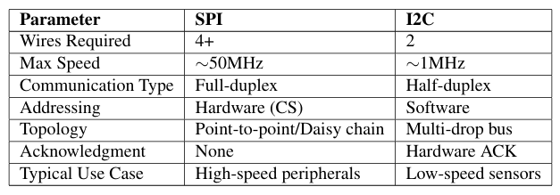
Table 1: SPI vs I2C Comparison
III.HARDWARE IMPLEMENTATION DETAILS
3.1 BoostXL Display Interface
The game utilizes the Texas Instruments BoostXL-EDUMKII display module with the following characteristics:
• Display Controller: SSD2119 SPI TFT Controller
• Resolution: 320×240 pixels (QVGA)
• Color Depth: 16-bit RGB (5-6-5 format)
• Communication Protocol:
- 4-wire SPI interface
- SCLK-Serial clock at 10MHz maximum
- MOSI-Data output from MCU to display
- D/C-Data/Command selection (replaces MISO)
- CS-Active low chip select
• Additional Connections:
- Reset line for hardware initialization
- Backlight control via PWM
3.2 MPU6050Motion Sensor
The InvenSense MPU6050 6-DoF IMU is integrated via I2C with these specifications:
• Default Address: 0x68 (configurable to 0x69 via AD0 pin)
• Sensor Features:
- 3-axis accelerometer (±2g/4g/8g/16g ranges)
- 3-axis gyroscope (±250/500/1000/2000◦/s)
- On-chip Digital Motion Processor (DMP)
- Programmable sample rate (1Hz to 8kHz)
• Communication Setup:
I 2C_Init ();
I2C_Write (0x6B, 0x00 );
I2C_Write (0x1B, 0x00 );
I2C_Write (0x1C, 0x00 );
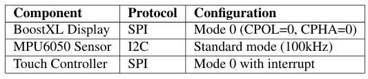
Table 2: Hardware Communication Protocols
3.3 System Integration
The hardware components interact through the following connections:
/ / SPI Pins for Display
#define DISPLAY_SCLK GPIO_PIN_3 // PF3
#define DISPLAY_MOSI GPIO_PIN_1 // PF1
#define DISPLAY_CS
GPIO_PIN_2 // PF2
#define DISPLAY_DC
/ / I2C Pins for MPU6050
#define MPU6050_SCL
#define MPU6050_SDA
GPIO_PIN_0 // PF0
GPIO_PIN_2 // PB2
GPIO_PIN_3 // PB3
Key integration considerations:
• SPI Bus Sharing: Display and touch controller share SPI bus with separate CS lines
• I2C Pull-ups: 4.7kΩ resistors on SDA/SCL lines
• Power Management:– Display: 3.3V with 150mA peak current– MPU6050: 3.3V with 3.5mA operating current
• Interrupt Handling: MPU6050 INT pin for data ready signals
IV.CONCLUSION
The Dino Game implementation successfully demonstrates several key concepts in embedded systems development:
• Multi-protocol Communication:
- Efficient SPI communication with the BoostXL display
- I2Cinterface with MPU6050 motion sensor
- Touch controller integration
• Real-time System Design:
- Fixed-time step game loop at 60FPS
- Physics calculations with gravity (a = GRAVITY)
- Collision detection using AABB and circular methods
• Resource Optimization:
- Selective redraw techniques
- Primitive-based rendering
- Efficient state management
• Responsiveness: 16ms frame time target achieved
• Visual Fidelity: 16-bit color at 320×240 resolution
• Game Balance: Progressive difficulty scaling via speed multiplier
4.1 Future Enhancements
Potential improvements include
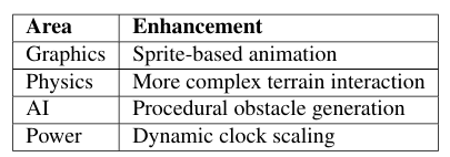
Table 3: Potential Future Improvements
The project serves as a comprehensive example of:
• Embedded game development constraints
• Hardware/software co-design
• Real-time system performance tuning
Recent Comments