
I.INTRODUCTION
In recent years, vehicle tracking and monitoring systems have become essential components in transportation safety, fleet management, and theft prevention. Inertial Navigation Systems (INS), using onboard motion sensors such as accelerometers, gyroscopes, and magnetometers offer a complementary solution by providing orientation and motion data. A virtual Compass shows the Vehicle’s orientation with the Magnetic North and can be used in Navigation. This project introduces a robust INS that incorporates the SIM900A GSM/GPRS module for remote communication, enabling real-time monitoring via cellular networks. Critical alerts are delivered via SMS to ensure immediate user awareness. To further enhance its utility, the system interfaces with the vehicle’s CAN bus, enabling access to diagnostic information such as Battery Status and any other fault codes. Together, these features create a comprehensive platform for intelligent vehicle monitoring and control. Here we will be discussing the System Block Diagram, Functions of Each module and Finally the Overall Working system developed.
II.BLOCK DIAGRAM
The system architecture comprises of the Tiva Launch Pad integrated with a sensor interface module. The Inertial Measurement Unit (IMU) and magnetometer are connected on a shared I2C bus, enabling synchronized acquisition of orientation and heading data. A user input switch is connected via a GPIO pin for control or mode selection. A real-time display is interfaced through the SPI bus to present dynamic navigation and system information. For wireless communication, the SIM900A GSM module is connected over UART, facilitating SMS data transmission. To simulate vehicle network communication, the system includes a secondary Launch Pad acting as a dummy Electronic Control Unit (ECU). This emulated ECU transmits real-time clock and battery status over the CAN bus to the main navigation module. The complete integration is illustrated in the block diagram below.
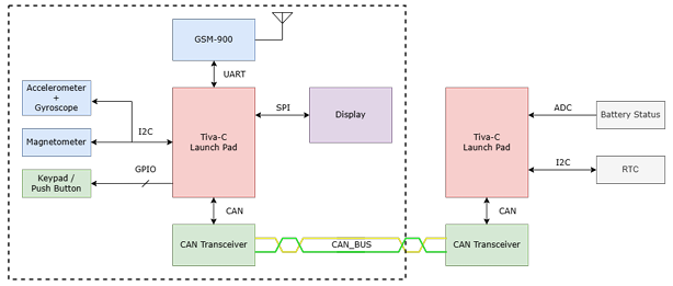
Figure 1: Block Diagram of the Navigation System
III.COMPONENT SPECIFICATION
3.1 Inertial Measurement Unit- MP6500
• Communicates with the IMU and magnetometer over I2C, operating at a standard clock frequency of 100kHz.
• Acceleration and gyroscope data are acquired in real-time and expressed in units of g(acceleration due to gravity) and degrees/second, respectively, along all three coordinate axes (X, Y, Z).
• Offset compensation is applied to correct for inherent sensor biases and eliminate cumulative drift errors.
• The resultant acceleration magnitude is calculated and compared against a predefined threshold to detect and flag motion events.
3.2 Magnetometer- HMC5883L
• The magnetometer communicates via the same I2C shared with IMU, using a standard SCL frequency of 100kHz.
• Measures magnetic field strength in micro teslas (µT) across all three coordinate axes (X, Y, Z).
• Requires compensation to correct for hard iron (offset) and soft iron (elliptical distortion) errors.
• The corrected magnetic field data is used to calculate the heading angle relative to magnetic north.
• The digital compass automatically adjusts based on the orientation of the magnetometer, ensuring accurate directional output.
3.3 2.8” TFT LCD Display- ILI9341
• A2.8-inch TFT LCD display is interfaced using the SPI protocol operating at a clock frequency of 8MHz.
• The display features a resolution of 240×320 pixels with 16-bit RGB color depth for rich visual output.
• Driven by the ILI9341 display controller, ensuring fast and reliable rendering.
• Used to display three categories of sensor data (e.g., orientation, acceleration, magnetic heading).
• A button press cycles through different data tabs, allowing the user to switch between sensor views interactively.
3.4 GSMModule-GSIM800A
• Communicates with the microcontroller via UART at a baud rate of 9600 bps.
• Operates using standard AT commands (e.g., AT+CMGF, AT+CMGS) for composing and sending SMS messages.
• Automatically triggers emergency SMS alerts when crash-level acceleration is detected by the IMU.
• Sends predefined location or status information to configured emergency contacts.
• Capable of responding to incoming SMS commands for remote status updates and system control actions.
IV.HARDWARE SYSTEM SETUP
V.M4C123PIN MAPPING
VI.IMPLEMENTATION
6.1 Calibration of Magnetometer
Calibration of Magnetometer is a crucial step before getting to use the raw Magnetic Field data. The surrounding places are prone to be magnetic in nature for example Iron or any other Ferro magnetic substances. These would induce biasing towards a particular axis. This is called Hard Iron or Offset Error. Sometimes the total scale of the Magnetic field on eacch axis varies with one another. This would create more variations in
one particular axis more than others. The overall structure created by plotting all the co ordinate axes would result in an ellipsoid rather than a sphere. This is called Soft Iron or Elliptical error. Such errors can be eliminated by proper compensation. Here we are taking a sample of 500 set of magnetic field values on all the 3 axes and finding out the Min and Max on each of X, Y and Z. The average of those min and max would give out the offset value and the difference gives the scaling value. Then the calibrated value is calculated by the formula:
Here, offset value corresponds to the Hard Iron and Sclaing value corresponds to the Soft Iron Compensation. Note that the compensation varies with the environment and places. Hence it is better to do compensation periodically. Here, the heading is calculated based on the field that is applied maximum onto the X-axis.
6.2 CAN communication via dummy ECU
The dummy ECU provides RTC and Battery level values via CAN to the Main Navigation module. The CAN protocol data-rate is set to 500kbps here. Initially, the RTC is set in the dummy ECU via UART.
The updated RTC also triggers CAN to send the corresponding Time and Date value. This updation of Date and Time would occur periodically at a rate of once every minute. Similarly when the Potentiometer of the ECU is changed, the value gets updated into the Navigation system for alerting the user. The updation of ADC occurs once every 5s. Coming to the Navigation system, After the Power Up, the Launch Pad in our Navigation system module initializes all the Connected sensors, Display module and GSM module. The dummy ECU unit here acts as an emulator for the Vehicle’s ECU, that is connected with the Navigation module via CAN. The Display in the Navigation System starts displaying one of the 3 screens. Each screen is used for different purposes and the views can be cycled by the SW1 switch.
6.3 Orientation Display
The digital compass accurately indicates the direction of magnetic North, along with the heading angle in degrees based on the device’s orientation. Prior to the operation, the magnetometer must be calibrated to ensure precise and reliable directional readings.(As described in the previous subsection). The screen refreshes at a rate of about 2Hz.
6.4 System Info Display
This Displays key system information including battery percentage, current system time, date along with GSM signal strength. CAN-based alerts are received and displayed in real-time for system monitoring and diagnostics.
6.5 Motion Data Display
This Displays the real-time acceleration of the module across all the three axes. Detects any sudden jerks or abnormal movements, triggering an on-screen alert. Simultaneously, an SMS notification is sent to alert the user in case of critical motion events.
From the above, there are 2 types of alert which gets triggered if either the Battery of the Vehicle is low or any sudden Jerks are felt on the IMU.
VII.STANDOUT FEATURES IMPLEMENTED
• The system is designed with a prioritized interrupt structure and optimized data structures to ensure efficient real-time
performance.
• Digital filtering techniques for noise reduction.
• State-based power management for energy efficiency.
• Adaptive calibration algorithm for maintaining sensor accuracy.
• Additionally, robust error handling with timeouts ensures reliable operation under various fault conditions.
VIII.DEVELOPMENT CHALLENGES
• Managing real-time constraints while acquiring and processing data from multiple sensors simultaneously.
• Optimizing memory usage to operate efficiently within the limited resources.
• Ensuring robust and reliable system performance in electrically noisy and vibration-prone automotive environments.
• Implementing accurate sensor calibration and drift compensation to maintain long-term measurement integrity.
• Maintaining reliable communication using the AT command protocol, even under poor signal or interrupted conditions.
IX.FUTURE SCOPE FOR IMPROVEMENTS
• GPS module Integration for precise positioning. Under dead-reckoning condition, the positioning is shifted to the secondary
sensors- IMU(primary now)
• Bluetooth or WiFi connectivity for Local data access and Cloud connectivity.
• Mobile Application Development for user friendly User Interface.
• Integration of ML for predictive maintenance and ADAS features.
• SoM or SoC based development for Linux based OS for more customization.
X.CONCLUSION
The GSM/GPRS-Enabled Inertial Navigation System represents a comprehensive solution for vehicle Navigation, monitoring, combining robust tracking capabilities with real-time communication for enhanced security and management applications.
Recent Comments