
I.INTRODUCTION
This project aims to design and implement a dual-channel function generator using the Tiva C Series TM4C123GH6PM LaunchPad board with the BOOSTXL-K350QVG-S1 QVGA touchscreen display. The system generates and visualizes standard waveforms- sine, square, triangle, and sawtooth- with configurable parameters such as frequency, amplitude, and duty cycle. A touchscreen-based graphical user interface allows real-time user interaction and waveform selection. Waveforms are rendered on the display using lookup tables and are updated dynamically using SysTick timer interrupts. The project demonstrates embedded system integration, graphical interface design, and real-time waveform processing in a resource-constrained microcontroller environment. [1]
II.COMPONENTS REQUIRED
The components used are BOOSTXL-K350QVG-S1 QVGA display, and TM4C123GH6PM Tiva C series board.
2.1 Kentec Touch Display
The BOOSTXL-K350QVG-S1isaKentecQVGADisplayBoosterPack™designed to interface with Texas Instruments LaunchPad™ board, the TM4C123GH6PM Tiva C Series microcontroller. It provides a graphical output and touch interface that enhances embedded system applications requiring user interaction.
2.1.1 Key Specifications of the LCD Display
[2]
• Display Type: TFT (Thin Film Transistor) LCD with a 3.5-inch diagonal screen
• Resolution: 320×240 pixels (QVGA)
• Touch Panel: 4-wire resistive touch
• Color Depth: 262,000 colors (18-bit RGB)
• Backlight: White LED with boost converter circuitry.
• Controller IC: SSD2119 LCD driver (built-in)
• Interface: SPI (default: 4-wire, 8-bit mode)
2.1.2 Working and Interface
The Kentec display uses the SSD2119 display controller, which communicates with the microcontroller through the Serial Peripheral Interface (SPI). The 4-wire SPI setup includes:
• LCD_SCS- Chip Select
• LCD_SCL- SPI Clock
• LCD_SDI- Serial Data Input
• LCD_SDC- Data/Command select line
This configuration supports high-speed communication with minimal pin usage. An optional 3-wire, 9-bit SPI mode is available by altering resistor configurations on the board, though 4-wire is the default and more widely supported.
The resistive touch screen utilizes four analog signals (XL, XR, YT, YB) to detect touch location via voltage drop detection. A touch controller driver in software processes these readings to map them to display coordinates.
2.1.3 Integration with Tiva C Launch Pad
The BOOSTXL-K350QVG-S1 conforms to the 40-pin Booster Pack standard and connects directly to the Tiva C Series Launch Pad. It receives 3.3V and 5V power, and utilizes dedicated SPI pins from the Tiva board. The SPI bus is shared between the LCD and the resistive touch panel. The provided TI graphics library (grlib) is used to initialize the screen, draw graphical primitives, and handle user input through the touch interface.
2.1.4 Backlight Control
The white LED backlight is powered using a dedicated boost converter circuit on the Booster Pack. The boost converter raises the supply voltage (typically from 5V) to approximately 20V to drive the backlight LEDs in series. The brightness can be modulated using PWM signals if required.
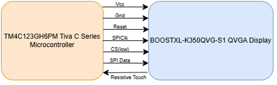
Figure 1: Block Diagram for interfacing VGA Display and Tiva C Series Microcontroller
III.KEY FEATURES
The function generator project using the TM4C123GH6PM Tiva C Launch Pad and BOOSTXL-K350QVG-S1 Kentec QVGA touch display has the following features:
• Multi-Waveform Support: Capable of generating and displaying four standard waveforms- sine, square, triangular, and sawtooth- for each of the two independent output channels.
• Frequency Generation: Supports waveform frequencies of up to 500 Hz or higher. Due to limitations in display resolution and real-time rendering, frequency scaling techniques are implemented to visually simulate higher frequencies without distortion on the 320×240 pixel display.
• Amplitude Control: Generates signal amplitudes of up to 3V peak, with visual scaling done to correctly represent amplitudes within the pixel height of the display.
• Duty Cycle Adjustment: For square waves, selectable duty cycles of 0%, 25%, 50%, 75%, and 100% are supported, allowing flexibility in digital waveform shape.
• Fine and Coarse Parameter Tuning:– Frequency: Coarse adjustment steps of 10 Hz, fine adjustment steps of 1 Hz.
• Amplitude: Coarse adjustment steps of 1 V, fine adjustment steps of 0.1 V.
These adjustments are implemented via touch-controlled buttons on the graphical interface.
• Dual-Channel Operation: The system supports two independent channels with separate frequency, amplitude, duty cycle, and waveform selection. Both channels are displayed and updated alternately using the SysTick timer to balance real-time performance.
• Touch-Based Graphical Interface: This GUI built using TI’s grlib allows users to [3]:– Navigate across screens (home, parameter selection, waveform viewer).– Modify waveform parameters in real time.
• Optimized Redraw Logic: The display is updated only when necessary (i.e., when waveform parameters change), which reduces screen flicker and enhances the system’s responsiveness.
• System Timing and Control: The SysTick timer is used to orchestrate periodic waveform updates, and display refresh events efficiently.
• Memory-Efficient Lookup Tables: Pre-computed lookup tables for each waveform type are stored and indexed dynamically to enable fast and efficient waveform generation.
3.1 Implementation Approach
The development of this dual-channel function generator involved a structured, modular approach combining embedded hardware initialization, graphical user interface design, signal generation logic, and real-time system control. The following subsections describe the method adopted in detail:
3.1.1 Hardware Initialization
• The Tiva TM4C123GH6PM microcontroller was configured by setting up the system clock and enabling necessary peripherals such as GPIO, UART, SPI, and SysTick timer.
• The BOOSTXL-K350QVG-S1 QVGA display was interfaced via the SPI bus and initialized using the Kentec320x240x16 ssd2119 spi driver.
• Floating Point Unit (FPU) support was enabled to accelerate floating-point computations, essential for waveform calculations like sine and triangle functions.
• The SysTick timer was configured to provide periodic interrupts for getting waveform updates.
3.1.2 Graphical User Interface Setup
• A Home screen was designed to allow the user to select waveform types for Channel 1 and Channel 2.
• Dedicated parameter adjustment screens were created for both channels to enable frequency, amplitude, and duty cycle tuning.
• Multi-screen navigation was implemented using touch-sensitive buttons labeled NEXT, HOME, and BACK.
3.1.3 Waveform Selection and Parameter Tuning
• For each channel, the user could select one of the four waveforms: sine, square, triangle, or sawtooth.
• Dedicated buttons were used to adjust frequency and amplitude values in both coarse and fine increments:– Coarse tuning: ±10 Hz for frequency, ±1 V for amplitude– Fine tuning: ±1 Hz for frequency, ±0.1 V for amplitude.
• Duty cycle adjustment (specific to square waves) was available in five discrete steps: 0%, 25%, 50%, 75%, and 100%.
• Each button press triggered call back functions to update internal parameters in real-time.
3.1.4 Waveform Generation Logic
• Lookup tables for each waveform type (sine, triangle, square, sawtooth) were precomputed and stored in memory.
• Waveform samples were generated using array indexing, scaled dynamically based on the selected frequency and amplitude.
• Dual-channel logic was implemented, enabling both channels to operate simultaneously with independent parameters.
• Waveforms were plotted using grlib primitives, and displayed on the QVGA screen in real-time.
3.1.5 SysTick Timer and Interrupt Handling
• The SysTick timer was set up to generate periodic interrupts for controlling system tasks.
• Within the SysTick handler, the system alternated updates between Channel 1 and Channel 2, reduces latency and balances the CPU load.
3.1.6 Optimization and Refresh Control
• Flags like refresh Ch1 Needed and refresh Ch2 Needed were employed to redraw waveform plots only when parameters had changed.
• The waveform parameters obtained previously were cached to detect changes and prevent unnecessary display updates, there by minimizing flickering and CPU usage.
• The use of hardware FPU ensured that all real-time waveform calculations were fast and efficient.
• The display resolution and refresh logic were calibrated to handle high-frequency waveform visualization with appropriate scaling techniques.
• Touch screen calibration and noise filtering mechanisms were implemented using the provided function Touch Screen Call back Set().
IV.CHALLENGES FACED
During the development of the dual- channel function generator project, several hardware and software challenges were encountered. These challenges influenced certain design decisions and imposed practical constraints on the system’s final functionality.
A detailed account is provided below:
• Conflict in SPI Peripheral Usage: The LTC1661 DAC was initially considered for real-time waveform output to a CRO. However, the SPI bus required by the DAC was already used by the LCD touchscreen. Due to this conflict and real-time constraints, the DAC was excluded, and waveform visualization was limited to the LCD.
• UART and LCD Configuration Conflict: An issue was encountered while configuring both UART and the LCD simultaneously. When UART was initialized for communication, the LCD display stopped responding, likely due to timing conflicts or shared resource contention. As a result, UART functionality was limited, and priority was given to maintaining stable LCD operation.
• Touchscreen Inaccuracy at Higher Voltages: When the amplitude was set above 3V, the touchscreen became unreliable, showing glitches or missing touches. This issue likely came from power or ADC limitations. To keep the system stable, the amplitude was limited to a maximum of 3V.
• Simultaneous Channel Handling: Managing two channels in real time was challenging. The SysTick timer was used to switch between Channel 1 and Channel 2 updates. At higher frequencies, this sometimes caused screen lag. This was reduced by using flags to control updates and UART transmission.
• Touchscreen Calibration and Button Sensitivity: At first, the touchscreen had trouble detecting button presses accurately due to noise and incorrect coordinate mapping. These issues caused inconsistent response across screens. The problem was improved by adjusting the touch call back and refining the button areas.
V.RESULT
The function generator interface was tested with different waveforms and parameter settings. The screenshots below illustrate various stages of user interaction, including home screen navigation, parameter tuning, waveform rendering, and system exit interface.
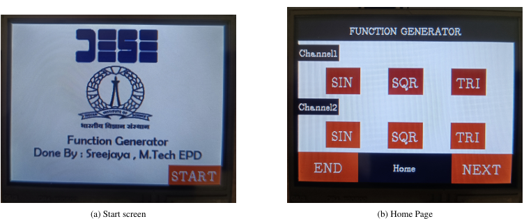
Figure 2: Start and home screens of the waveform generator
5.1 Future Scope and Advancements
The current implementation of the dual-channel function generator provides basic waveform generation and visualization using a touchscreen interface. Several enhancements and extensions can be made to increase the system’s capability, usability, and integration with external systems. Some possible advancements include:
• DAC Integration for Analog Output: Interfacing a Digital-to-Analog Converter (DAC) such as the LTC1661 or MCP4922 to output analog waveforms in real time.
• External Command Control via UART: Enabling bidirectional UART communication to allow a PC or external controller to send commands for waveform configuration, thus enabling remote operation or automation.
• SD Card Logging Support: Integrating SD card functionality to log parameter settings and waveform data for later analysis.
• Frequency and Amplitude Sweep Functionality: Adding sweep features to automatically vary frequency or amplitude over time, useful for signal analysis, sensor testing, or dynamic system response studies.
• PWM-based Analog Output (for testing): Implementing a filtered PWM output as a low-cost approximation of analog waveforms in the absence of a DAC, suitable for basic signal generation use cases.
• Advanced Touchscreen Features: Implementing multi-touch gestures, improved calibration, and real-time waveform annotation using graphical overlays.
• Web Interface or Bluetooth Control: Extending the system with Wi-Fi or Bluetooth modules (e.g., ESP8266, HC-05) to enable wireless control and monitoring through mobile apps or web dashboards.
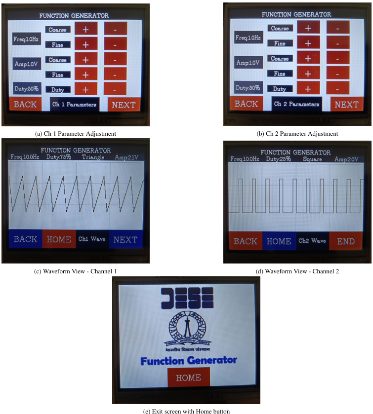
Figure 3: User interface for parameter setting, waveform display, and exit
VI.CONCLUSION
The function generator project successfully demonstrates the integration of waveform generation, graphical rendering, and touch based user interaction on a resource-constrained embedded platform. By utilizing the TM4C123GH6PM microcontroller and the Kentec QVGA touch screen display, a complete real-time dual-channel waveform visualization tool was implemented. The system supports standard waveforms with configurable parameters and provides a clear interface for parameter tuning and waveform inspection. The project showcases the capabilities of embedded systems in creating user-centric, interactive electronics and
provides a solid foundation for further enhancement such as DAC interfacing, remote control, and advanced signal analysis.
REFERENCES
[1] Texas Instruments. TM4C123GH6PM Microcontroller Datasheet. Texas Instruments, 2013.
[2] Texas Instruments. Boostxl-k350qvg-s1 kentec display boosterpack user guide, 2013. https://www.ti.com/tool/BOOSTXL-K350QVG-S1.
[3] Texas Instruments. Tiva C Series Graphics Library (grlib), 2013. Available in TivaWare package.
Recent Comments