
Abstract
Introducing a secure bootloader for TM4C123GH6PM Tiva Board, integrating advanced cryptography to au-
thenticate and encrypt firmware updates. This solution implements robust secure boot mechanisms, enhanc-
ing upgrade process integrity and reliability for field- deployed devices.
I Introduction
In the realm of embedded systems, the TM4C123GH6PMTiva Board serves as a versatile platform for diverse applications. As the connectivity of such devices continues toexpand, ensuring the integrity and security of firmware
updates becomes paramount. Our project focuses ondeveloping a robust and secure bootloader solution tai-lored specifically for the TM4C123GH6PM Tiva Board.
Leveraging advanced cryptographic techniques, notablythe RSA algorithm, our solution aims to authenticate and
encrypt firmware updates, mitigating potential securityvulnerabilities and unauthorized access.
Furthermore, our bootloader implementation enablesthe loading of two distinct applications during boot-time,
enhancing the flexibility and reliability of field-deployeddevices. By integrating secure boot mechanisms and
leveraging the capabilities of the Tiva Board, our so-lution provides a resilient framework for firmware up-
dates. Through this endeavor, we seek to fortify theTM4C123GH6PM Tiva Board against emerging security
threats, ensuring its continued operation in various de-ployment environments
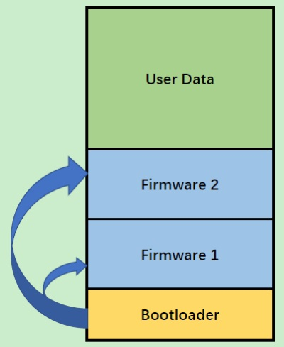
Figure 1: Boot Loader
In project components, we possess the versatility to em-ploy various communication protocols for interfacing with
the bootloader and uploading the user application. However, we have strategically chosen UART communication
due to its inherent simplicity and widespread compatibility. This selection streamlines the development process of
a user-friendly desktop application, serving as a versatileflashing utility for seamless firmware updates. By lever-
aging UART communication and harnessing the capabilities of the TM4C123GH6PM microcontroller, we aim to
deliver a sophisticated and efficient firmware upgrade solution tailored to the needs of modern embedded systems.
II Project Components
2.1
External libraries used
1. TI’s TivaWare library as MCAL layer: LeveragingTI’s TivaWare library as the Microcontroller Ab-
straction Layer (MCAL) not only ensures seamlessintegration with the TM4C123GH6PM Tiva Board
but also provides a rich set of functionalities and drivers, streamlining the development process and
enhancing the efficiency of firmware operations.
2. For CRC32 calculations PyCRC’s generated C library has been used: Utilizing PyCRC’s meticu-
lously generated C library for CRC32 calculations ensures high-performance and accurate checksum gen-
eration, bolstering data integrity and validation processes within the bootloader framework, thereby en-
hancing the reliability and security of firmware updates.
2.2Memory Map
The memory map delineates the allocation of memorywithin the TM4C123GH6PM Tiva Board, strategically
dividing it into distinct segments to accommodate variouscomponents of the firmware ecosystem. The bootloader
occupies the initial segment from address 0x00000000H to0x00005FFFH, with 24KBs reserved, despite the current
version requiring less than 6KBs, allowing ample spacefor future expansion and development iterations. This re-
served space ensures scalability and flexibility in adapting to evolving firmware requirements.Following this, a sizable free space from address
0x00006000H to 0x0000FFFFH is reserved to cater to Future expansion and dynamic memory needs, foster-
ing flexibility and scalability in firmware development Subsequently, Application 1 is allocated from address
0x00010000H to 0x00013FFFH, providing ample room for the deployment of the primary application code, with each
application occupying 16KBs of space. Likewise, Application 2 occupies the subsequent segment, spanning from
address 0x00014000H to 0x00017FFFH, enabling the isolation and independent execution of multiple application
instances. The delineation of memory blocks serves to optimize resource utilization, enhance system stability, and
facilitate seamless firmware updates and maintenance operations.
2.3packet structure:
To ensure reliable communication on UART a structuredpacket is transmitted for each command/chunk of data.
Each packet has 3 bytes overhead. The maximum usefuldata in a packet is 252 bytes ( 1% overhead). Below is
the packet structure:
• (0) Data length (n)
• (1) Opcode: determines the type of request/response
• (2 : (2+n-1)) Data
• (2+n) Terminator: A static value representing the
end of the packet (0xA5).
Upon successful reception of a packet, the bootloader
promptly acknowledges the transmission by echoing a re-
sponse packet, denoted by the bytes: 0x01, 0xAA, [re-
ceivedOpcode], 0xA5.
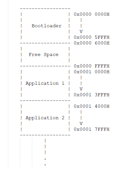
Figure 2: Memory Map
III Booting Sequence
The bootloader’s booting sequence orchestrates a stream-lined process for system initialization, application selec-
tion, and firmware updates, ensuring robustness and flexibility in firmware management. This concise overview
encapsulates the essential stages of the bootloader’s operation, from RAM execution to application launch, pro-
viding a foundation for efficient system startup and maintenance. Booting Sequence:
1. Startup Code Execution in RAM: Upon system reset, the bootloader’s startup code initiates by copy-
ing the firmware code into RAM and commencing execution from SRAM, ensuring optimal performance
and flexibility in runtime operations.
2. Initialization and Switch Detection: FollowingRAM execution, initialization routines are executed.
The bootloader then monitors the state of SW1 andSW2 push buttons on the LaunchPad, determining
whether to proceed to application 1 or application2, or to remain in the bootloader mode for firmware
updates.
3. Switch Functionality for Firmware Updates:
In scenarios where both applications are dumped,pressing both switches facilitates re-entry into the
bootloader execution mode. Subsequently, a doublepress of SW1 or SW2 enables the flashing of a new
binary file into the respective application 1 or application 2 areas, streamlining the firmware update
process.
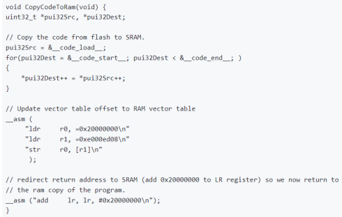
Figure 3: Booting Sequence
4. Application Area Integrity Check: Before transitioning to the application, the bootloader perform a validation check on the first 8 bytes of the application area. If these bytes are found erased, signifying 0xFFs, the bootloader refrains from jumping into the application, preventing erroneous execution. These
initial bytes serve a crucial role in determining the stack pointer and reset handler of the application.
IV Flashing Sequence
1. Erase (idle state only)
• Erase request
– Opcode: 0x01
– Data: N/A
• Erase response
– Opcode: 0xA1
– Data:
∗ 0x01 Erasing successful
∗ 0xF0 Erasing failed
2. Flashing request (idle state only)
– Opcode: 0x02
– Data: (4 bytes) Payload size (big-endian)
• Flashing request response
– Opcode: 0xA2
– Data:
∗ 0x01 Flashing accepted
∗ 0x00 Flashing refused
3. Flash data (only after accepted flashing request)
• Flash data request
– Opcode: 0x03
– Data: (max 252) Application data
• Flash data response
– Opcode: 0xA3
– Data:
∗ 0x00 Writing flash memory failed
∗ 0x01 Writing flash memory succeeded,
send next chunk of data
∗ 0x02 Writing flash memory succeeded,
application
4. Flash end
• Flash end request
– Opcode: 0x04
– Data: (4 bytes) CRC32
• Flash end response
– Opcode: 0xA4
– Data:
∗ 0x01 Received CRC matched calculated
CRC. This means the application is cor-
rectly received and flashed.
∗ 0x00 CRC mismatch. Failed flashing
operation.
5. Reset request: The MCU will reset immediately
V Conclusion
By leveraging advanced cryptographic techniques and ro-bust secure boot mechanisms, this project ensures the
authentication and encryption of firmware updates, mit-igating potential security vulnerabilities and unautho-
rized access. The integration of versatile communication protocols, such as UART, streamlines the firmware up-
date process, while the memory map optimization and packet structure enhance system stability and reliabil-
ity. Through the implementation of a streamlined boot-ing sequence and flashing sequence, our secure bootloader
provides a resilient framework for firmware management,safeguarding the TM4C123GH6PM Tiva Board against
emerging security threats in diverse deployment environments.
Recent Comments