
I ABSTRACT
Gesture recognition is an important feature in many applications. Currently, gesture-based controls are most successful in commercial
touch screens but are slowly gaining traction in industrial robotics applications as well. While gesture recognition can be achieved using
machine learning, it requires edge support for deploying these models. Another approach to gesture recognition is based on template
matching using algorithms like Dynamic Time Warping. In this mini-project, we aim to implement motion control using motors based on
gesture recognition data collected from a three-axis accelerometer. The platform chosen to demonstrate this is the Tiva TM4C123GH6PM
board launchpad.
I INTRODUCTION
Gesture control in robotics is an interesting area of research with significant potential for the future. Currently, most robots are
controlled by switches and knobs, which require practice and are less natural to operate. This gap can be filled by gesture-based
motion control. In this mini-project, we will utilize the ADXL335 three-axis accelerometer to record changes in acceleration
along the X, Y, and Z axes. The analog output from the ADXL335 is interfaced with the onboard ADC on the Tiva board and
stored in the onboard memory. The TM4C123GH6PM is a 32-bit ARM Cortex-M4-based micro controller with 256 KB Flash
memory, 32 KB SRAM, and 80 MHz operation. Since the acceleration data is not expected to change rapidly, the specifications
of the Tiva board are sufficient to implement gesture-based motion control.
II PROPOSED ALGORITHM
Dynamic Time Warping (DTW) is a technique used to compare two sequences of data that may vary in time or speed, commonly
employed in time series analysis, such as accelerometer data. In our project, we will collect accelerometer data from the sensor,
comprising measurements of acceleration along different axes (e.g., x, y, z) at regular time intervals. Prior to analysis, the data
undergoes pre-processing, which includes filtering (e.g., low-pass filtering to remove noise), normalization (e.g., scaling the data
to a common range), and segmentation (e.g., dividing the data into individual gestures or activities). For our current scope, we
have defined three segments: Up, Down, and Unrecognized. Additional segments may be added during the implementation
phase.
Once alignment and matching is done with the pre-stored gestures, command to control the Motor Driver will be send using
PWM or any digital interface. Three channels of the internal ADC inside micro controller will be used to convert the full range
of the accelerometer. The sample sequencer inside the TI micro controller is proposed to be used for storing the accelerometer
data in the FIFO memory. The ADC initialization and channel selection will be done by using the following registers.
1. RCGCADC: To enable the clock to ADC module.
2. RGCGPIO: To enable clock to GPIO port.
3. ADC0 EMUX R: To set the trigger for conversion.
4. ADC0 SSMUX3 R: To select the channel.
5. AFSEL: Select alternate function of GPIO pin.
6. AMSEL: To use analog function instead of digital function.
7. ADCSSCTL3 and ADCSAC: To set the interrupt bit, number of samples and hardware averaging.
8. ADCACTSS: Enable the sequencer.
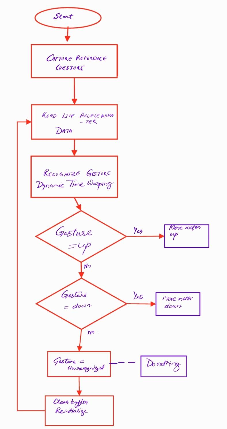
Figure 1: Flow chart for Motion Control based on gesture recognition
III CONCLUSION AND F UTURE SCOPE
The calibration process and the creation of standard templates need to be highly accurate and reproducible, and they will be
stored and labeled during the data collection phase. Since the micro controller lacks edge support, direct application of machine
learning to this node is not feasible. However, if the TI CC1352P (Cortex M4 48 MHz) is available, deployment of machine
learning models can be explored. The BOOSTXL module contains a 9-axis accelerometer MPU 9150, which will be evaluated
for comparison against the 3-axis accelerometer. The BOOSTXL module interfaces via I2C and will require a different module
for integration. Once the motion control design is completed, it can be utilized to control the Delta robot equipped with micro-
stepping motors via the RS485 MODBUS interface. A TTL-RS485 converter will facilitate the control of the delta robot and is
an extension of the project. The primary focus of the mini project is to incorporate more gestures and implement speed control
through gestures on simple servo/DC motors.
code: Gesture based Motion Control Using Dynamic Time Warping_final
Video: Motion Control based on Gesture recognition using TIVA board
Recent Comments