
Introduction
This project is implemented using STM32L Discovering board with an add-on board of IR Transmitter. It switches on/off the AC and can increase or decrease the temperature of AC.
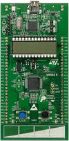
STM32L Discovery Board Details
The STM32L Discovery board is based on an STM32L152RBT6 and includes on-board ST-Link/V2 debug interface. As can be seen from the picture, most of the General Purpose I/Os (GPIOs) are brought out for use towards the sides of the board.
The main features of the board which were used in this project are:
   The external 3V supply pin which can be used to provide power to Buzzer and Accelerometer add-on boards
   The GPIO ports brought out to sides of the board
   Built-in I2C module
The programming of this board can be done on the open-source toolchain as described in the article – Getting Started with STM32L-Discovery Board, or on the evaluation version of Keil uVision platform.
Protocol
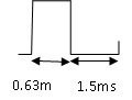
A message sent using this protocol consists of twenty eight bits. Sixteen of these bits is used for the address field and twelve bits for the key code and followed by high pulse. A Start bit (8.6 ms) is sent followed by a 4.1 ms space or pause. Next comes the data followed by stop bit (0.63ms). A ’1’ is represented by 0.63 ms ON and a 1.5 ms OFF or pause.
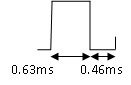
A ’0’ is represented by 0.63 ms ON and 0.46 ms OFF or pause.
A typical messages format: 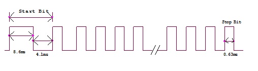
Principal and Configuration
The main principal used in the remote control is transmission of modulated pulses of infrared (IR) light between a remote control handset and the device it controls. The transmitter in the remote control handset sends out a unique stream of pulses of infrared light when the user presses a button on the handset. A transmitter is often a light emitting diode (LED) which is built into the pointing end of the remote control handset. The infrared light pulses form a pattern unique to that button. The receiver in the device recognizes the pattern and causes the device to respond accordingly
The command data is a Manchester coded bitstream modulating a 38 kHz carrier. The IR signal from the transmitter is detected by a specialized IC with an integral photo-diode, and is amplified, filtered, and demodulated so that the receiving device can act upon the received command. Micro-controller used on the STM32LDiscovery board is STM32L152RB.
Clock configuration – HSI internal clock 0f 16MHz is enabled and set as system clock. AHB and APB1 clocks are set to 16MHz and clocks for peripherals – TIM3 and TIM4 on APB1 and GPIOs on AHB- are configured.
16-bit Timers, TIM3 and TIM4 have been used in up mode for PWM generation. A 16-bit programmable prescaler register divides (also “on the fly”) the counter clock frequency by any factor between 1 and 65536.
An interrupt is generated on the event of counter overflow/underflow, output compare which has been used for loading the registers with the appropriate values for generating the unique pattern for a particular temperature of AC. The counter, the auto-reload register and the prescaler register can be written or read by software, even when the counter is running. The time-base unit includes: • Counter Register (TIMx_CNT) • Prescaler Register (TIMx_PSC): • Auto-Reload Register (TIMx_ARR)
The auto-reload register is preloaded. Writing to or reading from the auto-reload register accesses the preload register. The content of the preload register are transferred into the shadow register permanently or at each update event (UEV), depending on the auto-reload preload enable bit (ARPE) in TIMx_CR1 register. The update event is sent when the counter reaches the overflow and if the UDIS bit equals 0 in the TIMx_CR1 register. It can also be generated by software. The counter is clocked by the prescaler output, which is enabled only when the counter enable bit (CEN) in TIMx_CR1 register is set. The prescaler can divide the counter clock frequency by any factor between 1 and 65536. It can be changed on the fly as this control register is buffered. The new prescaler ratio is taken into account at the next update event.
Upcounting mode
In upcounting mode, the counter counts from 0 to the auto-reload value (content of the TIMx_ARR register), then restarts from 0 and generates a counter overflow event. An Update event can be generated at each counter overflow or by setting the UG bit in the TIMx_EGR register. When an update event occurs, all the registers are updated and the update flag (UIF bit in IMx_SR register) is set : • the buffer of the prescaler is reloaded with the preload value (content of the TIMx_PSC register) • the auto-reload shadow register is updated with the preload value (TIMx_ARR)
PWM mode
Pulse width modulation mode allows you to generate a signal with a frequency determined by the value of the TIMx_ARR register and a duty cycle determined by the value of the TIMx_CCRx register.
You must enable the corresponding preload register by setting the OCxPE bit in the TIMx_CCMRx register, and eventually the auto-reload preload register (in upcounting or center-aligned modes) by setting the ARPE bit in the TIMx_CR1 register. As the preload registers are transferred to the shadow registers only when an update event occurs, before starting the counter, you have to initialize all the registers by setting the UG bit in the TIMx_EGR register.
The Timer registers used are – TIMX control register TIMX_CRX TIMX status register TIMX_SR TIMX_prescaler TIMX_PSC TIMX_suto reload register TIMX_ARR TIMX_Capture/compare register TIMX_CCR
Three user buttons have been used – on/off, increment temp, decrement temp. Interrupt service routine on button press reloads the appropriate registers of the timer.
Circuit Diagram and Waveform
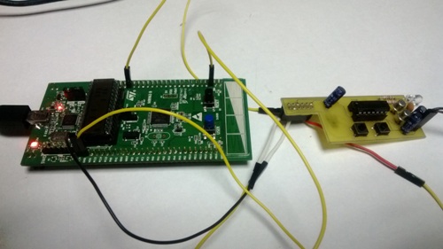
Test setup:
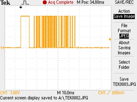
The transmitted AC ON waveform:
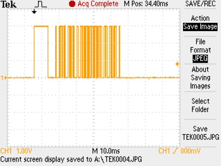
The transmitted AC OFF waveform:
Recent Comments